A sequential circuit has two JK flip-flops A and B and one input x. The circuit is described by the following flip-flop input equations:
A sequential circuit has two JK flip-flops A and B and one input x. The circuit is described by the following flip-flop input equations:
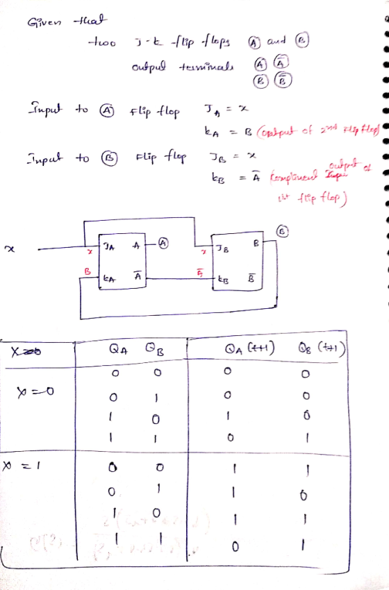
JA= x KA = B
JB = x Kb = A'
Find the state table and diagram of the circuit

Homework Answers
If you have any doubts please comment
If everything is clear please rate the answer
Thank you
Add Answer to:
A sequential circuit has two JK flip-flops A and B and one input x. The circuit is described by the following flip-flop input equations:
Q2: A sequential circuit has two JK flip-flops (FF) with outputs A and B and one...
 Q2: A sequential circuit has two JK flip-flops (FF) with outputs A and B and one input x. The circuit is described by the following flip-flop input equations: JA=X KA=B JB = x KB=A' (a) Derive the state equations A (t+1) and B (t+1) by substituting the input equations for the J and K variables in the characteristic equations of JK FF. (b) Construct the state Diagram of the circuit. (5+10-15) pts.
3. A sequential circuit has 2 JK flip-flops A and B and one input x. The...
 3. A sequential circuit has 2 JK flip-flops A and B and one input x. The circuit is described by the following flip-flop input equations: (a) Derive the state equations A(t1) and B(t +1) by substituting the input equations for the J and K variables (b) Draw the state diagram of the circuit (c) Design an equivalent circuit using D flip flops, i.e. a sequential circuit that uses D flip flops to implement the state diagram you obtained in part...
A sequential circuit with 2 JK flip-flops, A and B; 2 inputs, x and y;...
A sequential circuit with 2 JK flip-flops, A and B; 2 inputs, x and y; and 1 output, z is specified by the following next-state and output equations: JA=Bx + B'y' JB = A'x Z= Ax'y' + Bx'y' KA= B’xy' KB = A + xy' Draw the logic diagram of the circuit List the state table for the sequential circuit Draw the corresponding state diagram Derive the next state equation for A and B
The sequential circuit shown below has two flip-flops A and B and one input x. It...
 The sequential circuit shown below has two flip-flops A and B and one input x. It consists of a combinatorial logic connected to the flip-flops, as shown in the Figure 1. Below. Analyze the sequential circuit below: A J A' K Q lo B 2-to-1 MUX Y J Q 11 S B K CLK Figure 1a. Sequential Circuit a) Derive the next state equations for the sequential circuit above: find expressions for JA and KA and Jb and KB as...
Is this figure correct for the above problem? IA JA B cluck Ro 5.9 A sequential...
 Is
this figure correct for the above problem?
IA JA B cluck Ro 5.9 A sequential circuit has two JK flip-flops A and B and one input x. The circuit is described by the following flip-flop input equations: JA = x KA = B JB = x KB = A'
Is
this figure correct for the above problem?
IA JA B cluck Ro 5.9 A sequential circuit has two JK flip-flops A and B and one input x. The circuit is described by the following flip-flop input equations: JA = x KA = B JB = x KB = A'
ECE 260 HW 7 NAME 1. A sequential circuit has two JK flip-flops A and B,...
 ECE 260 HW 7 NAME 1. A sequential circuit has two JK flip-flops A and B, two inputs X and Y, and one output Z. The flip-flop input equations and circuit output equation are: (a) Draw the sequential circuit (b) Derive the state equations for Q and Q (c) Construct the state/output table (d) Draw the state diagram Note, for JK flip-flop: Q1O+KQ Design a sequential circuit with two JK flip-flops A and B and two inputs E and F....
03: 6 marks) Sequential circuit that has two flip-flops A and B and one input x...
 03: 6 marks) Sequential circuit that has two flip-flops A and B and one input x and a constant 'l'. It consists of a combinatorial logic connected to the JK flip-flops, as shown in Figure below. a. (2 marks) Derive the next state and output equations. b. (2 marks) Derive the state table of the sequential circuit. c. (2 marks) Draw the corresponding state diagram. K ā
A sequential circuit which is designed using JK Flip-Flops is given below. So, analyse (resolve) the...
 A sequential circuit which is designed using JK Flip-Flops is given below. So, analyse (resolve) the given sequential circuit and draw the corresponding state transition diagram. Also, write down required expressions and determine the sequential circuit model type. Qa should be considered MSB and Z is output. X Qb Ja Qal XI Ka Хаа- Jb Qbi -Z Qa- Kb
A sequential circuit has two D flip-flops, A and B, one input x and one output...
A sequential circuit has two D flip-flops, A and B, one input x and one output y. The flip-flop input functions and the output function are the folllowing: DA = Ax` + Bx DB= A`x + Bx` y = Ax + Bx a) Write the state table of the circuit b) Draw the state diagram of the circuit (note that the output changes when the input changes)
1. A sequential circuit has one JK flip-flop A, one input x, and one output y....
 1. A sequential circuit has one JK flip-flop A, one input x, and one output y. The flip-flop input equation and circuit output equation are: (a) Draw the logic diagram of the circuit (b) Tabulate the state table of the circuit (P. S., Input, N. S., Output). (c) Draw the state diagram. (d) Derive the state equation A(t+ 1). (e) Starting from state A 0 in the state diagram, determine the state transitions and output sequence that will be generated...
 Q2: A sequential circuit has two JK flip-flops (FF) with outputs A and B and one input x. The circuit is described by the following flip-flop input equations: JA=X KA=B JB = x KB=A' (a) Derive the state equations A (t+1) and B (t+1) by substituting the input equations for the J and K variables in the characteristic equations of JK FF. (b) Construct the state Diagram of the circuit. (5+10-15) pts.
 3. A sequential circuit has 2 JK flip-flops A and B and one input x. The circuit is described by the following flip-flop input equations: (a) Derive the state equations A(t1) and B(t +1) by substituting the input equations for the J and K variables (b) Draw the state diagram of the circuit (c) Design an equivalent circuit using D flip flops, i.e. a sequential circuit that uses D flip flops to implement the state diagram you obtained in part...
 The sequential circuit shown below has two flip-flops A and B and one input x. It consists of a combinatorial logic connected to the flip-flops, as shown in the Figure 1. Below. Analyze the sequential circuit below: A J A' K Q lo B 2-to-1 MUX Y J Q 11 S B K CLK Figure 1a. Sequential Circuit a) Derive the next state equations for the sequential circuit above: find expressions for JA and KA and Jb and KB as...
 Is
this figure correct for the above problem?
IA JA B cluck Ro 5.9 A sequential circuit has two JK flip-flops A and B and one input x. The circuit is described by the following flip-flop input equations: JA = x KA = B JB = x KB = A'
Is
this figure correct for the above problem?
IA JA B cluck Ro 5.9 A sequential circuit has two JK flip-flops A and B and one input x. The circuit is described by the following flip-flop input equations: JA = x KA = B JB = x KB = A'
 ECE 260 HW 7 NAME 1. A sequential circuit has two JK flip-flops A and B, two inputs X and Y, and one output Z. The flip-flop input equations and circuit output equation are: (a) Draw the sequential circuit (b) Derive the state equations for Q and Q (c) Construct the state/output table (d) Draw the state diagram Note, for JK flip-flop: Q1O+KQ Design a sequential circuit with two JK flip-flops A and B and two inputs E and F....
 03: 6 marks) Sequential circuit that has two flip-flops A and B and one input x and a constant 'l'. It consists of a combinatorial logic connected to the JK flip-flops, as shown in Figure below. a. (2 marks) Derive the next state and output equations. b. (2 marks) Derive the state table of the sequential circuit. c. (2 marks) Draw the corresponding state diagram. K ā
 A sequential circuit which is designed using JK Flip-Flops is given below. So, analyse (resolve) the given sequential circuit and draw the corresponding state transition diagram. Also, write down required expressions and determine the sequential circuit model type. Qa should be considered MSB and Z is output. X Qb Ja Qal XI Ka Хаа- Jb Qbi -Z Qa- Kb
 1. A sequential circuit has one JK flip-flop A, one input x, and one output y. The flip-flop input equation and circuit output equation are: (a) Draw the logic diagram of the circuit (b) Tabulate the state table of the circuit (P. S., Input, N. S., Output). (c) Draw the state diagram. (d) Derive the state equation A(t+ 1). (e) Starting from state A 0 in the state diagram, determine the state transitions and output sequence that will be generated...
Most questions answered within 3 hours.
-
Casey is on trial under criminal allegations that she engaged in
fraudulent behavior at the company...
asked 8 minutes ago -
1. A boy stands on one end of a boat, and then walks to the
other...
asked 3 minutes ago -
Surplus Styles is a manufacturer of hair care products,
including shampoos, conditioners, and hair gels. The...
asked 6 minutes ago -
Using an income-expenditure diagram, use the infinite line and
double-drop line tools to show the economy...
asked 15 minutes ago -
Which expression computes a pseudorandom integer between -10 and
10 using rand()
from cstdlib?
A. (rand(...
asked 21 minutes ago -
Roybus, Inc., a manufacturer of flash memory, just reported that
its main production facility in Taiwan...
asked 29 minutes ago -
Two capacitors connected in parallel produce an equivalent
capacitance of 45.0 μF but when connected in...
asked 38 minutes ago -
The differences between the two sets of dependent data are -1,
2,-,2, 2. Round to the...
asked 55 minutes ago -
A χ2-curve, looking at the relationship between age and hours
spent working at an office per...
asked 1 hour ago -
The pH of a sample of water from a river is 5.0. A
sample of effluent from...
asked 2 hours ago -
At the beginning of the period, the Fabricating Department
budgeted direct labor of $136,500 and equipment...
asked 2 hours ago -
Please answer all
____ 28. Rent control is usually
justified on the grounds that it protects...
asked 2 hours ago
> What is the state equation and how to derive it?
Ezio Auditore Mon, Nov 1, 2021 6:24 AM