
Homework Answers
Add Answer to:
The current in the RL circuit shown below reaches two-thirds its maximum value in 2.00 ms...
The current in the RL circuit shown below reaches three-fifths its maximum value in 3.75 ms...
 The current in the RL circuit shown below reaches three-fifths its maximum value in 3.75 ms after the switch S, is thrown. 0000 (a) Determine the time constant of the circuit (in ms). 7.34 x ms (b) Determine the resistance of the circuit (in ) if L = 150 mH.
RL Circuits The current in the RL circuit shown below reaches half its maximum value in...
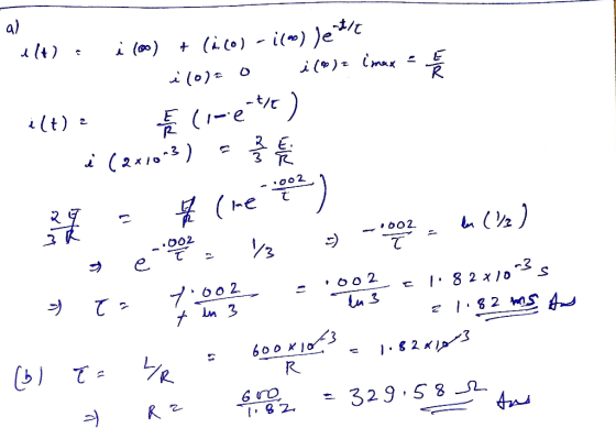
 RL Circuits The current in the RL circuit shown below reaches half its maximum value in 1.75 ms after the switch S1 is thrown. Determine (a) the time constant of the circuit and (b) the resistance of the circuit if L = 250 mH.
My Notes oSUniPhys1 31.4. P.057. 0/1 points Previous Answers The current in the RL circuit shown...
 My Notes oSUniPhys1 31.4. P.057. 0/1 points Previous Answers The current in the RL circuit shown below reaches four-fifths its maximum value in 1.50 ms after the switch S, is thrown. L R S1 (a) Determine the time constant of the circuit (in ms) 67.22213 Xms (b) Determine the resistance of the circuit (in Q) if L = 200 mH. 29.7525
In a RL series circuit, the current reaches half its maximum value in 2.0 s after...
 In a RL series circuit, the current reaches half its maximum
value in 2.0 s after the switch is closed. If the resistance is 5.0
Ω, find the inductance of the inductor. (4 pts)
In a RL series circuit, the current reaches half its maximum value in 2.0 s after the switch is closed. 5) If the resistance is 5.0 Ω, find the inductance of the inductor. (4 pts)
In a RL series circuit, the current reaches half its maximum
value in 2.0 s after the switch is closed. If the resistance is 5.0
Ω, find the inductance of the inductor. (4 pts)
In a RL series circuit, the current reaches half its maximum value in 2.0 s after the switch is closed. 5) If the resistance is 5.0 Ω, find the inductance of the inductor. (4 pts)
It takes 2.21 ms for the current in an LR circuit to increase from zero to 0.55 its maximum value. a. Determine the...
It takes 2.21 ms for the current in an LR circuit to increase from zero to 0.55 its maximum value. a. Determine the time constant of the circuit. b. Determine the resistance of the circuit if L = 34.0 mH.
1. An RL circuit comprised of one resistor and one inductor is shown in the figure below. The resistor and inductor...
 1. An RL circuit comprised of one resistor and one inductor is shown in the figure below. The resistor and inductor are connected to a source of emf with negligible internal resistance by a switch a. The emf for this circuit is 12.0 V. The resistance of the resistor is 0.35 , and the inductance of the inductor is 53 mH. For the circuit below: a. Sketch the graph of current through the inductor as a function of time after...
1. An RL circuit comprised of one resistor and one inductor is shown in the figure...
 1. An RL circuit comprised of one resistor and one inductor is shown in the figure below. The resistor and inductor are connected to a source of emf with negligible internal resistance by a switch a. The emf for this circuit is 12.0 V. The resistance of the resistor is 0.35 12, and the inductance of the inductor is 53 mH. For the circuit below: a. Sketch the graph of current through the inductor as a function of time after...
Help please ...! An RL circuit comprised of one resistor and one inductor is shown in...
 Help please ...!
An RL circuit comprised of one resistor and one inductor is shown in the figure below. The resistor and inductor are connected to a source of emf with negligible internal resistance by a switch a. The emf for this circuit is 12.0 V. The resistance of the resistor is 0.35 Q, and the inductance of the inductor is 53 mH. For the circuit below: Sketch the graph of current through the inductor as a function of time...
Help please ...!
An RL circuit comprised of one resistor and one inductor is shown in the figure below. The resistor and inductor are connected to a source of emf with negligible internal resistance by a switch a. The emf for this circuit is 12.0 V. The resistance of the resistor is 0.35 Q, and the inductance of the inductor is 53 mH. For the circuit below: Sketch the graph of current through the inductor as a function of time...
Please help, I'm struggling. Thank you An RL circuit comprised of one resistor and one inductor...
 Please help, I'm struggling. Thank you
An RL circuit comprised of one resistor and one inductor is shown in the figure below. The resistor and inductor are connected to a source of emf with negligible internal resistance by a switch a. The emf for this circuit is 12.0V. The resistance of the resistor is 0.35 12, and the inductance of the inductor is 53 mH. For the circuit below: a. Sketch the graph of current through the inductor as a...
Please help, I'm struggling. Thank you
An RL circuit comprised of one resistor and one inductor is shown in the figure below. The resistor and inductor are connected to a source of emf with negligible internal resistance by a switch a. The emf for this circuit is 12.0V. The resistance of the resistor is 0.35 12, and the inductance of the inductor is 53 mH. For the circuit below: a. Sketch the graph of current through the inductor as a...
 The current in the RL circuit shown below reaches three-fifths its maximum value in 3.75 ms after the switch S, is thrown. 0000 (a) Determine the time constant of the circuit (in ms). 7.34 x ms (b) Determine the resistance of the circuit (in ) if L = 150 mH.
 My Notes oSUniPhys1 31.4. P.057. 0/1 points Previous Answers The current in the RL circuit shown below reaches four-fifths its maximum value in 1.50 ms after the switch S, is thrown. L R S1 (a) Determine the time constant of the circuit (in ms) 67.22213 Xms (b) Determine the resistance of the circuit (in Q) if L = 200 mH. 29.7525
 In a RL series circuit, the current reaches half its maximum
value in 2.0 s after the switch is closed. If the resistance is 5.0
Ω, find the inductance of the inductor. (4 pts)
In a RL series circuit, the current reaches half its maximum value in 2.0 s after the switch is closed. 5) If the resistance is 5.0 Ω, find the inductance of the inductor. (4 pts)
In a RL series circuit, the current reaches half its maximum
value in 2.0 s after the switch is closed. If the resistance is 5.0
Ω, find the inductance of the inductor. (4 pts)
In a RL series circuit, the current reaches half its maximum value in 2.0 s after the switch is closed. 5) If the resistance is 5.0 Ω, find the inductance of the inductor. (4 pts)
 1. An RL circuit comprised of one resistor and one inductor is shown in the figure below. The resistor and inductor are connected to a source of emf with negligible internal resistance by a switch a. The emf for this circuit is 12.0 V. The resistance of the resistor is 0.35 , and the inductance of the inductor is 53 mH. For the circuit below: a. Sketch the graph of current through the inductor as a function of time after...
 1. An RL circuit comprised of one resistor and one inductor is shown in the figure below. The resistor and inductor are connected to a source of emf with negligible internal resistance by a switch a. The emf for this circuit is 12.0 V. The resistance of the resistor is 0.35 12, and the inductance of the inductor is 53 mH. For the circuit below: a. Sketch the graph of current through the inductor as a function of time after...
 1. An RL circuit comprised of one resistor and one inductor is shown in the figure below. The resistor and inductor are connected to a source of emf with negligible internal resistance by a switch a. The emf for this circuit is 12.0 V. The resistance of the resistor is 0.35 12, and the inductance of the inductor is 53 mH. For the circuit below: a. Sketch the graph of current through the inductor as a function of time after...
 Help please ...!
An RL circuit comprised of one resistor and one inductor is shown in the figure below. The resistor and inductor are connected to a source of emf with negligible internal resistance by a switch a. The emf for this circuit is 12.0 V. The resistance of the resistor is 0.35 Q, and the inductance of the inductor is 53 mH. For the circuit below: Sketch the graph of current through the inductor as a function of time...
Help please ...!
An RL circuit comprised of one resistor and one inductor is shown in the figure below. The resistor and inductor are connected to a source of emf with negligible internal resistance by a switch a. The emf for this circuit is 12.0 V. The resistance of the resistor is 0.35 Q, and the inductance of the inductor is 53 mH. For the circuit below: Sketch the graph of current through the inductor as a function of time...
 Please help, I'm struggling. Thank you
An RL circuit comprised of one resistor and one inductor is shown in the figure below. The resistor and inductor are connected to a source of emf with negligible internal resistance by a switch a. The emf for this circuit is 12.0V. The resistance of the resistor is 0.35 12, and the inductance of the inductor is 53 mH. For the circuit below: a. Sketch the graph of current through the inductor as a...
Please help, I'm struggling. Thank you
An RL circuit comprised of one resistor and one inductor is shown in the figure below. The resistor and inductor are connected to a source of emf with negligible internal resistance by a switch a. The emf for this circuit is 12.0V. The resistance of the resistor is 0.35 12, and the inductance of the inductor is 53 mH. For the circuit below: a. Sketch the graph of current through the inductor as a...
Most questions answered within 3 hours.
-
A university administrator working in student housing wants to
determine if the percentage of students residing...
asked 23 seconds from now -
A
projectile is blue at a target. The distance from the point of
impact to the...
asked 21 minutes ago -
Given a 32 bit processor, with 2 MB of physical RAM split into 512
frames. What...
asked 11 minutes ago -
What were the main rulings in the Supreme Court cases which are
Morgan v. Virginia (1946)...
asked 10 minutes ago -
write a five paragraph essay on how setting,
specifically culture, influences the actions of
the characters...
asked 2 minutes ago -
JAVA
Provide a simple code sample of Merge sort
asked 13 minutes ago -
Discounting cash flows involves:
A. taking the cash discount offered on a trade merchandise
B. estimating...
asked 20 minutes ago -
A solid wood door 1.00 m wide and 2.00 m high is hinged along
one side...
asked 20 minutes ago -
Raleigh Company manufactures two joint products. At the
split-off point, they have sales values of:
Product...
asked 20 minutes ago -
1. Your grandmother has invested $4000 in a mutual fund each
year on your birthday (she...
asked 22 minutes ago -
HELP WITH SAS
Run the following DATA step to create a SAS data set called
ABC_CORP....
asked 35 minutes ago -
A researcher wishes to study the cumulative effects of several
combinations of HIV drugs. There are...
asked 54 minutes ago