

Homework Answers
Add Answer to:
Chapter 31, Problem 047 An RLC circuit such as that of Figure (a) has R =...
An RLC circuit such as that of Figure (a) has R = 6.792, C = 18.3...
 An RLC circuit such as that of Figure (a) has R = 6.792, C = 18.3 uF, L = 1.38 H, and em = 24.4 V. (a) At what angular frequency od will the current amplitude have its maximum value, as in the resonance curves of Figure (b)? (b) What is this maximum value? At what (c) lower angular frequency wd1 and (d) higher angular frequency Wd2 will the current amplitude be half this maximum value? (e) What is (@d2...
An RLC circuit such as that of Figure (a) has R = 5.25 Ω, C =...
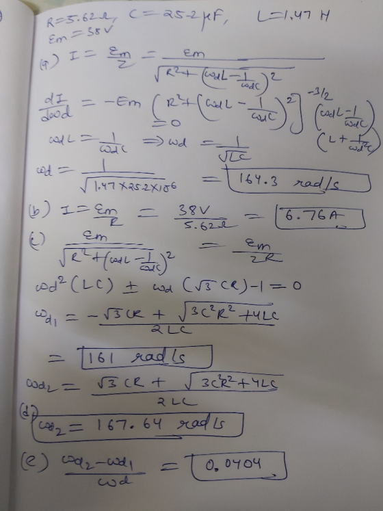
 An RLC circuit such as that of Figure (a) has R = 5.25 Ω, C =
25.1 μF, L = 1.47 H, and εm = 37.9 V. (a) At what angular frequency
ωd will the current amplitude have its maximum value, as in the
resonance curves of Figure (b)? (b) What is this maximum value? At
what (c) lower angular frequency ωd1 and (d) higher angular
frequency ωd2 will the current amplitude be half this maximum
value? (e) What is...
An RLC circuit such as that of Figure (a) has R = 5.25 Ω, C =
25.1 μF, L = 1.47 H, and εm = 37.9 V. (a) At what angular frequency
ωd will the current amplitude have its maximum value, as in the
resonance curves of Figure (b)? (b) What is this maximum value? At
what (c) lower angular frequency ωd1 and (d) higher angular
frequency ωd2 will the current amplitude be half this maximum
value? (e) What is...
i have done part a and b i need help with the rest An RLC circuit...
 i have done part a and b i need help with
the rest
An RLC circuit such as that of Figure (a) has R = 4.00 2, C = 27.0 pF, L = 1.32 H, and Em = 43.7 V. (a) At what angular frequency od will the current amplitude have its maximum value, as in the resonance curves of Figure (b)? (b) What is this maximum value? At what (c) lower angular frequency wd1 and (d) higher angular frequency...
i have done part a and b i need help with
the rest
An RLC circuit such as that of Figure (a) has R = 4.00 2, C = 27.0 pF, L = 1.32 H, and Em = 43.7 V. (a) At what angular frequency od will the current amplitude have its maximum value, as in the resonance curves of Figure (b)? (b) What is this maximum value? At what (c) lower angular frequency wd1 and (d) higher angular frequency...
Chapter 31, Problem 048 GO The figure shows a driven RLC circuit that contains two identical...
 Chapter 31, Problem 048 GO The figure shows a driven RLC circuit that contains two identical capacitors and two switches. The emf amplitude is set at 11.6 V, and the driving frequency is set at 55.3 Hz. With both switches open, the current leads the emf by 30.3°. With switch S, closed and switch S2 still open, the emf leads the current by 15.0°. With both switches closed, the current amplitude is 444 mA. What are (a) R, (b), and...
In an RLC circuit, assume ω, and ω2 such that 1(joi) = 1(ju).) = Imax/V2 and Δω such that Δω-: ω2...
 In an RLC circuit, assume ω, and ω2 such that 1(joi) = 1(ju).) = Imax/V2 and Δω such that Δω-: ω2-ω| . In other words, Δω is the width of the current curve where the current has fallen to 1/V2 = 0.707 of its maximum value at the resonance frequency. At these frequencies, the power dissipated in a resistance becomes one-half of the dissipated power at the resonance frequency (they are called the half-power points). In an RLC circuit with...
Chapter 31, Problem 036 An alternating source with a variable frequency, a capacitor with capacitance C,...
 Chapter 31, Problem 036 An alternating source with a variable frequency, a capacitor with capacitance C, and a resistor with resistance R are connected in series. The figure gives the impedance Z of the circuit versus the driving angular frequency wd; the curve reaches an asymptote of 650 2, and the horizontal scale is set by ads = 362 rad/s. The figure also gives the reactance Xc for the capacitor versus wd. What are (a) R and (b) C? Z...
Chapter 31, Problem 045 (a) In an RLC circuit, can the amplitude of the voltage across...
 Chapter 31, Problem 045 (a) In an RLC circuit, can the amplitude of the voltage across an inductor be greater than the amplitude of the generator emf? (b) Consider an RLC circuit with driving emf amplitude Em-8 V resistance R = 9 Ω, inductance L = 1.0 H, and capacitance C = 1.1 μF. Find the amplitude of the voltage across the inductor at resonance (b) Number Units the tolerance is +/-596
Chapter 31, Problem 034 GO Your answer is partially correct. Try again. In the figure, an...
 Chapter 31, Problem 034 GO Your answer is partially correct. Try again. In the figure, an ac generator with emf E = Em sin mot, where Em = 25.5 V and ad = 372 rad/s, is connected to a 4.48 uF capacitor. (a) What is the maximum value of the current? (b) When the current is a maximum, what i increasing in magnitude, what is the current? the emf of the generator? (c) When the emf of the generator is...
Consider the RLC circuit below, with R= 20 12, L = 10 mH, and C =...
 Consider the RLC circuit below, with R= 20 12, L = 10 mH, and C = 5 mF. The voltage source has a voltage amplitude of 26.0 V and an angular frequency of w = 500 rad/s. a) What is the total impedance of the circuit? b) Find the amplitude of the current, and the phase angle, d. c) Draw a phasor diagram of the impedances. Be sure to clearly label Z, R, XL, Xc, and 0. R C E
= 4.25 uF, and the inductance Consider a series RLC circuit where the resistance R =...
 = 4.25 uF, and the inductance Consider a series RLC circuit where the resistance R = 753 12, the capacitance C L 15.0 mH. Determine the resonance frequency 0 of the circuit. 00 rad/s What is the maximum current Imax when the circuit is at resonance, if the amplitude of the AC driving voltage is 60.0 V? Imax = A
 An RLC circuit such as that of Figure (a) has R = 6.792, C = 18.3 uF, L = 1.38 H, and em = 24.4 V. (a) At what angular frequency od will the current amplitude have its maximum value, as in the resonance curves of Figure (b)? (b) What is this maximum value? At what (c) lower angular frequency wd1 and (d) higher angular frequency Wd2 will the current amplitude be half this maximum value? (e) What is (@d2...
 An RLC circuit such as that of Figure (a) has R = 5.25 Ω, C =
25.1 μF, L = 1.47 H, and εm = 37.9 V. (a) At what angular frequency
ωd will the current amplitude have its maximum value, as in the
resonance curves of Figure (b)? (b) What is this maximum value? At
what (c) lower angular frequency ωd1 and (d) higher angular
frequency ωd2 will the current amplitude be half this maximum
value? (e) What is...
An RLC circuit such as that of Figure (a) has R = 5.25 Ω, C =
25.1 μF, L = 1.47 H, and εm = 37.9 V. (a) At what angular frequency
ωd will the current amplitude have its maximum value, as in the
resonance curves of Figure (b)? (b) What is this maximum value? At
what (c) lower angular frequency ωd1 and (d) higher angular
frequency ωd2 will the current amplitude be half this maximum
value? (e) What is...
 i have done part a and b i need help with
the rest
An RLC circuit such as that of Figure (a) has R = 4.00 2, C = 27.0 pF, L = 1.32 H, and Em = 43.7 V. (a) At what angular frequency od will the current amplitude have its maximum value, as in the resonance curves of Figure (b)? (b) What is this maximum value? At what (c) lower angular frequency wd1 and (d) higher angular frequency...
i have done part a and b i need help with
the rest
An RLC circuit such as that of Figure (a) has R = 4.00 2, C = 27.0 pF, L = 1.32 H, and Em = 43.7 V. (a) At what angular frequency od will the current amplitude have its maximum value, as in the resonance curves of Figure (b)? (b) What is this maximum value? At what (c) lower angular frequency wd1 and (d) higher angular frequency...
 Chapter 31, Problem 048 GO The figure shows a driven RLC circuit that contains two identical capacitors and two switches. The emf amplitude is set at 11.6 V, and the driving frequency is set at 55.3 Hz. With both switches open, the current leads the emf by 30.3°. With switch S, closed and switch S2 still open, the emf leads the current by 15.0°. With both switches closed, the current amplitude is 444 mA. What are (a) R, (b), and...
 In an RLC circuit, assume ω, and ω2 such that 1(joi) = 1(ju).) = Imax/V2 and Δω such that Δω-: ω2-ω| . In other words, Δω is the width of the current curve where the current has fallen to 1/V2 = 0.707 of its maximum value at the resonance frequency. At these frequencies, the power dissipated in a resistance becomes one-half of the dissipated power at the resonance frequency (they are called the half-power points). In an RLC circuit with...
 Chapter 31, Problem 036 An alternating source with a variable frequency, a capacitor with capacitance C, and a resistor with resistance R are connected in series. The figure gives the impedance Z of the circuit versus the driving angular frequency wd; the curve reaches an asymptote of 650 2, and the horizontal scale is set by ads = 362 rad/s. The figure also gives the reactance Xc for the capacitor versus wd. What are (a) R and (b) C? Z...
 Chapter 31, Problem 045 (a) In an RLC circuit, can the amplitude of the voltage across an inductor be greater than the amplitude of the generator emf? (b) Consider an RLC circuit with driving emf amplitude Em-8 V resistance R = 9 Ω, inductance L = 1.0 H, and capacitance C = 1.1 μF. Find the amplitude of the voltage across the inductor at resonance (b) Number Units the tolerance is +/-596
 Chapter 31, Problem 034 GO Your answer is partially correct. Try again. In the figure, an ac generator with emf E = Em sin mot, where Em = 25.5 V and ad = 372 rad/s, is connected to a 4.48 uF capacitor. (a) What is the maximum value of the current? (b) When the current is a maximum, what i increasing in magnitude, what is the current? the emf of the generator? (c) When the emf of the generator is...
 Consider the RLC circuit below, with R= 20 12, L = 10 mH, and C = 5 mF. The voltage source has a voltage amplitude of 26.0 V and an angular frequency of w = 500 rad/s. a) What is the total impedance of the circuit? b) Find the amplitude of the current, and the phase angle, d. c) Draw a phasor diagram of the impedances. Be sure to clearly label Z, R, XL, Xc, and 0. R C E
 = 4.25 uF, and the inductance Consider a series RLC circuit where the resistance R = 753 12, the capacitance C L 15.0 mH. Determine the resonance frequency 0 of the circuit. 00 rad/s What is the maximum current Imax when the circuit is at resonance, if the amplitude of the AC driving voltage is 60.0 V? Imax = A
Most questions answered within 3 hours.
-
At the start of a CD it is spinning at a rate of 525 rpm
(revolutions...
asked 9 minutes ago -
4. Without doing any calculations, predict whether the observed
∆T would increase, decrease or remain the...
asked 1 hour ago -
Based on the range, which of the following sets of scores has
the greatest variability? 3,...
asked 2 hours ago -
Ripples in a pond travel at a velocity of 3 m/s with one peak
passing a...
asked 2 hours ago -
A man stands on the roof of a building of height 13.0 mm and
throws a...
asked 2 hours ago -
The extent to which assets are financed by borrowed funds and
other liabilities is indicated by:...
asked 3 hours ago -
Explain in detail
Germany is the fifth largest economy
explain what goods and services Germany specializes...
asked 3 hours ago -
The density of platinum is 21.45 g/mL. If a cube of platinum
with a mass of...
asked 3 hours ago -
Accounts Receivable
Sales
A/R Posting
Extended Sales Invoice
Packing Slip
Compare invoice to packing slip 2...
asked 3 hours ago -
Michaella, age 23, is a full-time law student and is claimed by
her parents as a...
asked 3 hours ago -
Why are polymers not typically casted into products?
asked 4 hours ago -
When rolling a die 129 times, what is the probability of rolling
a 6 no more...
asked 4 hours ago