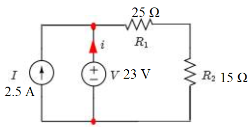
Calculate the power in Watts supplied by the current source in the circuit shown
Homework Answers

Add Answer to:
Calculate the power in Watts supplied by the current source in
the circuit shown
25 Ω...
For the circuit shown in Fig. 6, calculate:(a) the current in the 2.00−Ω resistor.(b) the potential...
 For the circuit shown in Fig. 6, calculate:(a) the current in
the 2.00−Ω resistor.(b) the potential difference between points a
and b.
Assume that the components on Fig. 7 have the following
values:V1 = 10.0 V , V2 = 15.0 V , R1 = 5.0 Ω, R1 = 5.00 Ω, R2 =
10.0 Ω, R3 = 15.0 Ω, R4 = 20.0 Ω. (a) Find the current trough each
branch of the circuit. (b) Find the power dissipated in each
circuit...
For the circuit shown in Fig. 6, calculate:(a) the current in
the 2.00−Ω resistor.(b) the potential difference between points a
and b.
Assume that the components on Fig. 7 have the following
values:V1 = 10.0 V , V2 = 15.0 V , R1 = 5.0 Ω, R1 = 5.00 Ω, R2 =
10.0 Ω, R3 = 15.0 Ω, R4 = 20.0 Ω. (a) Find the current trough each
branch of the circuit. (b) Find the power dissipated in each
circuit...
For the circuit shown in Fig. 10-12, calculate the current supplied by the voltage source and...
 For the circuit shown in Fig. 10-12, calculate the current supplied by the voltage source and the voltage across the current source. V, 500 2.8345° A 1 3:25 n 100/0° v Fig. 10-12
Consider the circuit below, consisting of a single power source and five resistors. The values in...
Consider the circuit below, consisting of a single power source and five resistors. The values in the circuit are as follows: ε = 24.9 V R1 = 22.9 Ω R2 = 13.0 Ω R3 = 148.3 Ω R4 = 131.1 Ω R5 = 97.0 Ω Calculate the current (Io) supplied by the power source. Use units of "A" or "Amps" for the current.
For the circuit below, determine, a. The equivalent resistance. b. The total current in the circuit. c. The total power. d. The current and voltage for R5 and R7 . Take, V = 48 V, R1 = 25 Ω, R5 = 45 Ω...
 For the circuit below, determine,
a. The equivalent resistance.
b. The total current in the circuit.
c. The total power.
d. The current and voltage for R5 and R7
.
Take, V = 48 V, R1 = 25 Ω, R5 = 45 Ω, R6 = 40 Ω, and R7 = 38
Ω.
2. 10] For the circuit below, determine, a. The equivalent resistance b. The total current in the circuit. c. The total power d. The current and voltage for...
For the circuit below, determine,
a. The equivalent resistance.
b. The total current in the circuit.
c. The total power.
d. The current and voltage for R5 and R7
.
Take, V = 48 V, R1 = 25 Ω, R5 = 45 Ω, R6 = 40 Ω, and R7 = 38
Ω.
2. 10] For the circuit below, determine, a. The equivalent resistance b. The total current in the circuit. c. The total power d. The current and voltage for...
Consider the circuit as shown below. R-2 92 Use Kirchoff's rules to calculate (a) the current...
 Consider the circuit as shown below. R-2 92 Use Kirchoff's rules to calculate (a) the current through each resistor: Le. R1: [IR1] A R2: [IR2] A R3: [IR3] A R4: [IR4] A (b) the power supplied by each DC source;i.e. V1: [P1] Watts v2: [P2] Watts v3: [P3] Watts and (c) the power dissipated in each resistor; L.e. R1: [PR1] Watts R2: [PR2] Watts R3: [PR3] watts R4: [PR4] watts IR1 is equal to ?? Amps Answer: IR2 is equal...
25 Ω 350 70 Ω 15 A 20 Ω 25 Ω Given: The circuit shown above....
 25 Ω 350 70 Ω 15 A 20 Ω 25 Ω Given: The circuit shown above. Required: Calculate the resistance value of R and the power, P, consumed by that resistor Solution R=
In the circuit shown in the figure below R1 . 42 Ω, R2 = 5.9 Ω, R3-32 Ω, li . 2.5 A, 4.7 A and i = 1.5 A. Calculate the power produced (or consumed) by the emf E2. (Give your answer in algebraic...
 In the circuit shown in the figure below R1 . 42 Ω, R2 = 5.9 Ω, R3-32 Ω, li . 2.5 A, 4.7 A and i = 1.5 A. Calculate the power produced (or consumed) by the emf E2. (Give your answer in algebraic decimal: (+) if the emf produces electrical power and ㈠ of the emf consumes electrical power. Use "W" as unit) e1 Ri Ry R2 112
In the circuit shown in the figure below R1 . 42...
In the circuit shown in the figure below R1 . 42 Ω, R2 = 5.9 Ω, R3-32 Ω, li . 2.5 A, 4.7 A and i = 1.5 A. Calculate the power produced (or consumed) by the emf E2. (Give your answer in algebraic decimal: (+) if the emf produces electrical power and ㈠ of the emf consumes electrical power. Use "W" as unit) e1 Ri Ry R2 112
In the circuit shown in the figure below R1 . 42...
In the circuit below, the voltage supplied by the power source is 10 V and the...
 In the circuit below, the voltage supplied by the power source
is 10 V and the current flowing through the circuit is 0.12
A.
KE3 Prelaboratory Questions E3 - Question 1: Resistance in a Circuit 1 of 5 Review 1 Constants i Periodic Table Part A In the circuit below, the voltage supplied by the power source is 10 V and the current flowing through the circuit is 0.12 A What is the resistance R2? 35 S2 33.75 Submit Previous...
In the circuit below, the voltage supplied by the power source
is 10 V and the current flowing through the circuit is 0.12
A.
KE3 Prelaboratory Questions E3 - Question 1: Resistance in a Circuit 1 of 5 Review 1 Constants i Periodic Table Part A In the circuit below, the voltage supplied by the power source is 10 V and the current flowing through the circuit is 0.12 A What is the resistance R2? 35 S2 33.75 Submit Previous...
I am trying get the power supplied by the source and the power factor. I keep...
 I am trying get the power supplied by the source and the power
factor. I keep getting 0 watts and 1 for the power factor. Could
you please assist me in why im not getting a number for the power
and a number in between .85-.95 for the power factor. What should
the power factor and power supplied be?
XHMI R1 w 150 R2 Wattmeter-XWM1 0.000 W 3300 C1 1.73 F Power factor: 1.00000 V1 5Vpk 100Hz 0° Voltage Current...
I am trying get the power supplied by the source and the power
factor. I keep getting 0 watts and 1 for the power factor. Could
you please assist me in why im not getting a number for the power
and a number in between .85-.95 for the power factor. What should
the power factor and power supplied be?
XHMI R1 w 150 R2 Wattmeter-XWM1 0.000 W 3300 C1 1.73 F Power factor: 1.00000 V1 5Vpk 100Hz 0° Voltage Current...
In the circuit shown in (Figure 1), R1=3 Ω , R2=5 Ω , R3=4 Ω ,...
 In the circuit shown in (Figure 1), R1=3 Ω , R2=5 Ω , R3=4 Ω ,
R4=9 Ω , and R5=9 Ω .
Part A: What is the current flowing through resistor R1 (A)?
Part B: What is the current flowing through resistor R2
(A)?
Part C: What is the current flowing through resistor R3 (A)?
Part D: What is the total power supplied by the battery (W)?
ㄱ
In the circuit shown in (Figure 1), R1=3 Ω , R2=5 Ω , R3=4 Ω ,
R4=9 Ω , and R5=9 Ω .
Part A: What is the current flowing through resistor R1 (A)?
Part B: What is the current flowing through resistor R2
(A)?
Part C: What is the current flowing through resistor R3 (A)?
Part D: What is the total power supplied by the battery (W)?
ㄱ
 For the circuit shown in Fig. 6, calculate:(a) the current in
the 2.00−Ω resistor.(b) the potential difference between points a
and b.
Assume that the components on Fig. 7 have the following
values:V1 = 10.0 V , V2 = 15.0 V , R1 = 5.0 Ω, R1 = 5.00 Ω, R2 =
10.0 Ω, R3 = 15.0 Ω, R4 = 20.0 Ω. (a) Find the current trough each
branch of the circuit. (b) Find the power dissipated in each
circuit...
For the circuit shown in Fig. 6, calculate:(a) the current in
the 2.00−Ω resistor.(b) the potential difference between points a
and b.
Assume that the components on Fig. 7 have the following
values:V1 = 10.0 V , V2 = 15.0 V , R1 = 5.0 Ω, R1 = 5.00 Ω, R2 =
10.0 Ω, R3 = 15.0 Ω, R4 = 20.0 Ω. (a) Find the current trough each
branch of the circuit. (b) Find the power dissipated in each
circuit...
 For the circuit shown in Fig. 10-12, calculate the current supplied by the voltage source and the voltage across the current source. V, 500 2.8345° A 1 3:25 n 100/0° v Fig. 10-12
 For the circuit below, determine,
a. The equivalent resistance.
b. The total current in the circuit.
c. The total power.
d. The current and voltage for R5 and R7
.
Take, V = 48 V, R1 = 25 Ω, R5 = 45 Ω, R6 = 40 Ω, and R7 = 38
Ω.
2. 10] For the circuit below, determine, a. The equivalent resistance b. The total current in the circuit. c. The total power d. The current and voltage for...
For the circuit below, determine,
a. The equivalent resistance.
b. The total current in the circuit.
c. The total power.
d. The current and voltage for R5 and R7
.
Take, V = 48 V, R1 = 25 Ω, R5 = 45 Ω, R6 = 40 Ω, and R7 = 38
Ω.
2. 10] For the circuit below, determine, a. The equivalent resistance b. The total current in the circuit. c. The total power d. The current and voltage for...
 Consider the circuit as shown below. R-2 92 Use Kirchoff's rules to calculate (a) the current through each resistor: Le. R1: [IR1] A R2: [IR2] A R3: [IR3] A R4: [IR4] A (b) the power supplied by each DC source;i.e. V1: [P1] Watts v2: [P2] Watts v3: [P3] Watts and (c) the power dissipated in each resistor; L.e. R1: [PR1] Watts R2: [PR2] Watts R3: [PR3] watts R4: [PR4] watts IR1 is equal to ?? Amps Answer: IR2 is equal...
 25 Ω 350 70 Ω 15 A 20 Ω 25 Ω Given: The circuit shown above. Required: Calculate the resistance value of R and the power, P, consumed by that resistor Solution R=
 In the circuit shown in the figure below R1 . 42 Ω, R2 = 5.9 Ω, R3-32 Ω, li . 2.5 A, 4.7 A and i = 1.5 A. Calculate the power produced (or consumed) by the emf E2. (Give your answer in algebraic decimal: (+) if the emf produces electrical power and ㈠ of the emf consumes electrical power. Use "W" as unit) e1 Ri Ry R2 112
In the circuit shown in the figure below R1 . 42...
In the circuit shown in the figure below R1 . 42 Ω, R2 = 5.9 Ω, R3-32 Ω, li . 2.5 A, 4.7 A and i = 1.5 A. Calculate the power produced (or consumed) by the emf E2. (Give your answer in algebraic decimal: (+) if the emf produces electrical power and ㈠ of the emf consumes electrical power. Use "W" as unit) e1 Ri Ry R2 112
In the circuit shown in the figure below R1 . 42...
 In the circuit below, the voltage supplied by the power source
is 10 V and the current flowing through the circuit is 0.12
A.
KE3 Prelaboratory Questions E3 - Question 1: Resistance in a Circuit 1 of 5 Review 1 Constants i Periodic Table Part A In the circuit below, the voltage supplied by the power source is 10 V and the current flowing through the circuit is 0.12 A What is the resistance R2? 35 S2 33.75 Submit Previous...
In the circuit below, the voltage supplied by the power source
is 10 V and the current flowing through the circuit is 0.12
A.
KE3 Prelaboratory Questions E3 - Question 1: Resistance in a Circuit 1 of 5 Review 1 Constants i Periodic Table Part A In the circuit below, the voltage supplied by the power source is 10 V and the current flowing through the circuit is 0.12 A What is the resistance R2? 35 S2 33.75 Submit Previous...
 I am trying get the power supplied by the source and the power
factor. I keep getting 0 watts and 1 for the power factor. Could
you please assist me in why im not getting a number for the power
and a number in between .85-.95 for the power factor. What should
the power factor and power supplied be?
XHMI R1 w 150 R2 Wattmeter-XWM1 0.000 W 3300 C1 1.73 F Power factor: 1.00000 V1 5Vpk 100Hz 0° Voltage Current...
I am trying get the power supplied by the source and the power
factor. I keep getting 0 watts and 1 for the power factor. Could
you please assist me in why im not getting a number for the power
and a number in between .85-.95 for the power factor. What should
the power factor and power supplied be?
XHMI R1 w 150 R2 Wattmeter-XWM1 0.000 W 3300 C1 1.73 F Power factor: 1.00000 V1 5Vpk 100Hz 0° Voltage Current...
 In the circuit shown in (Figure 1), R1=3 Ω , R2=5 Ω , R3=4 Ω ,
R4=9 Ω , and R5=9 Ω .
Part A: What is the current flowing through resistor R1 (A)?
Part B: What is the current flowing through resistor R2
(A)?
Part C: What is the current flowing through resistor R3 (A)?
Part D: What is the total power supplied by the battery (W)?
ㄱ
In the circuit shown in (Figure 1), R1=3 Ω , R2=5 Ω , R3=4 Ω ,
R4=9 Ω , and R5=9 Ω .
Part A: What is the current flowing through resistor R1 (A)?
Part B: What is the current flowing through resistor R2
(A)?
Part C: What is the current flowing through resistor R3 (A)?
Part D: What is the total power supplied by the battery (W)?
ㄱ
Most questions answered within 3 hours.
-
How do ethical issues affect decision making and what ethical
issues do you see in the...
asked 1 second ago -
The premium on a June 17 British pound call option with a strike
price of $1.2560...
asked 2 minutes ago -
Calculate the moment
of inertia (in kg·m2) of a skater given the following
information.
(a)
The...
asked 15 minutes ago -
A small body of mass m performs small oscillations sliding (no
rolling) along the bottom of...
asked 19 minutes ago -
The electric field in the region between two oppositely charged,
parallel, conducting plates has a magnitude...
asked 18 minutes ago -
A simple random sample was taken to test the claim that the
population mean is no...
asked 1 hour ago -
A set of length measurements are obtained with the values 165.6
± 0.3, 165.1± 0.4,166.4± 1.0,...
asked 1 hour ago -
1. Which of the following is true about unconscionable
contracts?
a. A term is substantially unconscionable...
asked 33 minutes ago -
A company is interested in estimating the costs of lunch
in their cafeteria. After surveying employees,...
asked 1 hour ago -
A 0.2m diameter ball with an initial velocity of 8m/s rolls up a
hill without slipping....
asked 48 minutes ago -
I want to redraft the solution, using other words , use your own
words don't copy...
asked 36 minutes ago -
Hyundai Motors is considering threesites—A, B,C —at which to
locate a factory to build its new-model...
asked 39 minutes ago