
Homework Answers


Add Answer to:
5.5 Select the values of R and Re in the circuit in Fig. P5.28 so that...
5.20 The op amp in the circuit shown in Fig, P5.20 is ideal, Calculate v, when v, equals 3 V b) S...
 5.20 The op amp in the circuit shown in Fig, P5.20 is ideal, Calculate v, when v, equals 3 V b) Specify the range of values of vg so that the op amp operates in a linear mode. c) Assume that a's equals 5 V and that the 48n resistor is replaced with a variable resistor. What value of the variable resistor will cause the op amp to saturate? Figure P5.20 48 kΩ 15 kΩ 10 V 30 kΩ 10...
5.4 The op amp in the circuit of Fig. P5.19 is ideal. a) What op amp...
 5.4 The op amp in the circuit of Fig. P5.19 is ideal. a) What op amp circuit configuration is this? b) Find in terms of us . c) Find the range of values for e, such that e, does nol saturate and thc op amp remains in its lincar region of operation. Figure P5.19 40 kΩ 10 V 12 kΩ 10 V 1 S1DE
Solve by using basic node-voltage or superposition! The op amp in the circuit of Fig. P5.23...
 Solve by using basic node-voltage or superposition! The op amp in the circuit of Fig. P5.23 is ideal. a) What op amp circuit configuration is this? b) Find vo in terms of vs c) Find the range of values for such that does not saturate and the op amp remains in its linear region of operation. Figure P5.23 96 kΩ 24 kΩ 10 V 16 kΩ 10V 24 kΩ
100 k22 RE R1 vo-w 20 ΚΩ ER vo + İPUCU: -Avi The Op-Amp used in...
 100 k22 RE R1 vo-w 20 ΚΩ ER vo + İPUCU: -Avi The Op-Amp used in the circuit in the figure is not ideal (i.e. for an internal resistance (Ri)): = V/V) resistors (R1, RF and Ri). Take a) First, regain the gain expression of the circuit in (Av the open loop gain A of the Op-Amp. b) Values given in the figure and R = 1 ks2, 10 ks, 100 ke ve 1 Calculate the gain separately for the...
63 k12 The Op Amp in the circuit shown in Fig. 1 is ideal, 30 k02...
 63 k12 The Op Amp in the circuit shown in Fig. 1 is ideal, 30 k02 12 V 12 k 12 - 12 V + a. Calculate vo when Vg equals 4 V. b. Specify the range of values of vg so that the Op Amp operates in a linear mode. c. Assume that Vg equals 2 V and that the 63 K12 resistor is replaced with a variable resistor. What value of the variable resistor will cause the Op...
5-4: The following circuit contains an ideal op-amp. The variable feedback resistor Re is adjusted until...
 5-4: The following circuit contains an ideal op-amp. The variable feedback resistor Re is adjusted until the op-amp saturates. Determine the value of R Re 1.6 kΩ 9 V 7.5 kΩ 9 V 18 V 1.5 kΩ 5-5: The following circuit contains an ideal op-amp. Assume Va = 1V, VB-1.5V, and Vc =-4V. Find the value of Vo. 220 kΩ 44 kΩ 10 V + 27.5 kΩ 80 k2 10 V 0a D)
1) Calculate the output voltage using the circuit of Fig for resistor components of value R=470Kohm...
 1) Calculate the output voltage using the circuit of Fig for resistor components of value R=470Kohm R=4.3 Kohm R=33Kohm & Rg=33Kohm (20) 2) Interpret the applications of op-Amp based on the ideal And Practical op-Amp characteristics (10)
Problem 1) [15 marks] The gain of the dual-op-axap instrumentation amplifier shown in Fig. 1 can be adjusted by the variable resistor Ro. The op-amps are ideal. atu Fig. 1 a)Show that v.-2(1 RG )...
 Problem 1) [15 marks] The gain of the dual-op-axap instrumentation amplifier shown in Fig. 1 can be adjusted by the variable resistor Ro. The op-amps are ideal. atu Fig. 1 a)Show that v.-2(1 RG )(v2-v.). b Specify suitable components to have a variable gain from 10 to 100 V/V. Problem 2) [15 marks] a) Design an op-amp limiter circuit for amplitude control with the transfer characteristic of Fig. 2(a). Use +-15V DC sources to power the circuit. Assume Vo-0.7 V...
The schematic circuit of a noninverting amplifier is shown in Fig.1a
 The schematic circuit of a noninverting amplifier is shown in Fig.1aThe circuit specifications are: V1=0.1V Again=30dB R3=100kΩ R1=10kΩ(a) Determine the output voltage of the amplifier, assume the op-amp is ideal.(b) Determine the resistance of R2, assume the op-amp is ideal.(c) Does the value of R1 affect the output of the amplifier, if the op-amp is
ideal? Justify your answer.(d) Does the value of R1 affect the output of the amplifier, if the op-amp is
non-ideal and has only an input offset voltage shown in...
The schematic circuit of a noninverting amplifier is shown in Fig.1aThe circuit specifications are: V1=0.1V Again=30dB R3=100kΩ R1=10kΩ(a) Determine the output voltage of the amplifier, assume the op-amp is ideal.(b) Determine the resistance of R2, assume the op-amp is ideal.(c) Does the value of R1 affect the output of the amplifier, if the op-amp is
ideal? Justify your answer.(d) Does the value of R1 affect the output of the amplifier, if the op-amp is
non-ideal and has only an input offset voltage shown in...
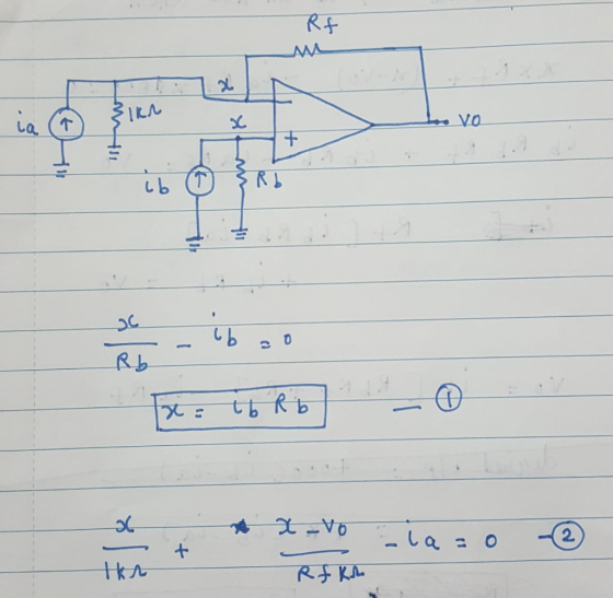
EE 261 Homework #6 Due in class on Oct. 10 (Wed) 5.6 The op aimp in...
 EE 261 Homework #6 Due in class on Oct. 10 (Wed) 5.6 The op aimp in the following circuit is ideal. Calculate a) ia. b) vai c) voi d) io. 5.11 The op amp in the circuit is ideal. The 500 resistor is adjustable between 0Ω σ : 0 and 50Ω (σ-: 1). a) Find the range of values for σ in which the op amp does not saturate. b) Find i', (in microamperes) when σ 0.272. 5.24 The circuit...
 5.20 The op amp in the circuit shown in Fig, P5.20 is ideal, Calculate v, when v, equals 3 V b) Specify the range of values of vg so that the op amp operates in a linear mode. c) Assume that a's equals 5 V and that the 48n resistor is replaced with a variable resistor. What value of the variable resistor will cause the op amp to saturate? Figure P5.20 48 kΩ 15 kΩ 10 V 30 kΩ 10...
 5.4 The op amp in the circuit of Fig. P5.19 is ideal. a) What op amp circuit configuration is this? b) Find in terms of us . c) Find the range of values for e, such that e, does nol saturate and thc op amp remains in its lincar region of operation. Figure P5.19 40 kΩ 10 V 12 kΩ 10 V 1 S1DE
 Solve by using basic node-voltage or superposition! The op amp in the circuit of Fig. P5.23 is ideal. a) What op amp circuit configuration is this? b) Find vo in terms of vs c) Find the range of values for such that does not saturate and the op amp remains in its linear region of operation. Figure P5.23 96 kΩ 24 kΩ 10 V 16 kΩ 10V 24 kΩ
 100 k22 RE R1 vo-w 20 ΚΩ ER vo + İPUCU: -Avi The Op-Amp used in the circuit in the figure is not ideal (i.e. for an internal resistance (Ri)): = V/V) resistors (R1, RF and Ri). Take a) First, regain the gain expression of the circuit in (Av the open loop gain A of the Op-Amp. b) Values given in the figure and R = 1 ks2, 10 ks, 100 ke ve 1 Calculate the gain separately for the...
 63 k12 The Op Amp in the circuit shown in Fig. 1 is ideal, 30 k02 12 V 12 k 12 - 12 V + a. Calculate vo when Vg equals 4 V. b. Specify the range of values of vg so that the Op Amp operates in a linear mode. c. Assume that Vg equals 2 V and that the 63 K12 resistor is replaced with a variable resistor. What value of the variable resistor will cause the Op...
 5-4: The following circuit contains an ideal op-amp. The variable feedback resistor Re is adjusted until the op-amp saturates. Determine the value of R Re 1.6 kΩ 9 V 7.5 kΩ 9 V 18 V 1.5 kΩ 5-5: The following circuit contains an ideal op-amp. Assume Va = 1V, VB-1.5V, and Vc =-4V. Find the value of Vo. 220 kΩ 44 kΩ 10 V + 27.5 kΩ 80 k2 10 V 0a D)
 1) Calculate the output voltage using the circuit of Fig for resistor components of value R=470Kohm R=4.3 Kohm R=33Kohm & Rg=33Kohm (20) 2) Interpret the applications of op-Amp based on the ideal And Practical op-Amp characteristics (10)
 Problem 1) [15 marks] The gain of the dual-op-axap instrumentation amplifier shown in Fig. 1 can be adjusted by the variable resistor Ro. The op-amps are ideal. atu Fig. 1 a)Show that v.-2(1 RG )(v2-v.). b Specify suitable components to have a variable gain from 10 to 100 V/V. Problem 2) [15 marks] a) Design an op-amp limiter circuit for amplitude control with the transfer characteristic of Fig. 2(a). Use +-15V DC sources to power the circuit. Assume Vo-0.7 V...
 EE 261 Homework #6 Due in class on Oct. 10 (Wed) 5.6 The op aimp in the following circuit is ideal. Calculate a) ia. b) vai c) voi d) io. 5.11 The op amp in the circuit is ideal. The 500 resistor is adjustable between 0Ω σ : 0 and 50Ω (σ-: 1). a) Find the range of values for σ in which the op amp does not saturate. b) Find i', (in microamperes) when σ 0.272. 5.24 The circuit...
Most questions answered within 3 hours.
-
suppose there is a normally distributed population with a mean of
250 and a standard deviation...
asked 39 minutes ago -
Question Three
Suppose you as project manager are using the Waterfall
development methodology on a large...
asked 1 hour ago -
Which statement is not true about welfare in Canada?
A.Benefits typically vary based on one's ability...
asked 2 hours ago -
Please help me with FLOWCHART and UML diagram for class,
thank you!
#include <iostream>
#include <fstream>...
asked 2 hours ago -
3. Describe the “logic circuit” of the Lac operon. Which
proteins are bound or not to...
asked 2 hours ago -
Ayesha’s adjusted gross income is $60,000 in 2019. She donated a
piece of artwork with a...
asked 3 hours ago -
For Dijkstra’s shortest path algorithm:
a. Give the Big-O time for Dijkstra’s shortest path algorithm
and...
asked 3 hours ago -
Phosphorus violates the 'octet rule' in biological molecules,
forming more covalent bonds than expected based on...
asked 3 hours ago -
A 1.3 eV electron has a 10-4 probability of tunneling
through a 2.4 eV potential barrier....
asked 3 hours ago -
What is the one ingredient that is common to being successful
with all stakeholders?
profit
trust...
asked 3 hours ago -
Write an assembly language 32 bit program that reads in lines of
text by a .txt...
asked 3 hours ago -
what is the density ( in g/L) of hydrogen gas at 29 degrees C and a...
asked 3 hours ago