
Homework Answers
Add Answer to:
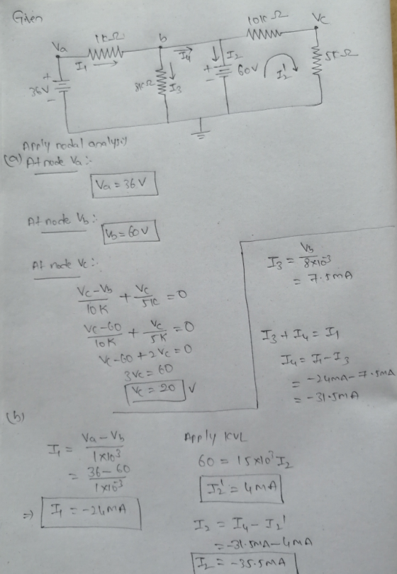
11. For the network of Fig. 7.74: a. Find the voltages Va, V, and V b....
For the circuit shown in figure 7, find the node voltages Vi. V2 and Va nalysis 12 (4 V 2Ω 4 A Fig.7 h. For the circuit...
 For the circuit shown in figure 7, find the node voltages Vi. V2 and Va nalysis 12 (4 V 2Ω 4 A Fig.7 h. For the circuit shown in figure 7, find the mesh currents I, la, and Is
For the circuit shown in figure 7, find the node voltages Vi. V2 and Va nalysis 12 (4 V 2Ω 4 A Fig.7 h. For the circuit shown in figure 7, find the mesh currents I, la, and Is
For the circuit shown in figure 7, find the node voltages Vi. V2 and Va nalysis 12 (4 V 2Ω 4 A Fig.7 h. For the circuit shown in figure 7, find the mesh currents I, la, and Is
Consider the network of Fig Pl.1. (a) 1. Label all node voltages and branch (b) Use the principle of superposition to (c) Determine the voltages v, V2, and v;3 i, l 80 Ω 50cos2000t V currents....
 Consider the network of Fig Pl.1. (a) 1. Label all node voltages and branch (b) Use the principle of superposition to (c) Determine the voltages v, V2, and v;3 i, l 80 Ω 50cos2000t V currents. 100 Ω 40 mHv, compute the currents io, il, i2, i3, and 4. + 24 v (d) Determine the power from the three S602 sources in the circuit
Consider the network of Fig Pl.1. (a) 1. Label all node voltages and branch (b) Use...
Consider the network of Fig Pl.1. (a) 1. Label all node voltages and branch (b) Use the principle of superposition to (c) Determine the voltages v, V2, and v;3 i, l 80 Ω 50cos2000t V currents. 100 Ω 40 mHv, compute the currents io, il, i2, i3, and 4. + 24 v (d) Determine the power from the three S602 sources in the circuit
Consider the network of Fig Pl.1. (a) 1. Label all node voltages and branch (b) Use...
For the circuit shown in Fig. , find the val- ues of all labeled currents and...
 For the circuit shown in Fig. , find the val- ues of all labeled currents and voltages for the B = 100. Assume V BEI = VEB2 = 0.7 V. +15V 200 ΚΩ 10k TE2 1 k12 - Vez 182 Tai IBI Vai VBIO- Q Icz va - Vez -o Ver 100 kΩ: 10 kΩ 1kΩ =
solve plz 790 III SERIES PARALLEL ac NETWORKS 11. For the network in Fig. 17.48: 2....
 solve plz
790 III SERIES PARALLEL ac NETWORKS 11. For the network in Fig. 17.48: 2. Find the total impedance Z b. Find the source current in phasor form 6. Find the currents L and I in phisor form. d. Find the voltages V and V. in phasor form. e. Find the average power delivered to the nel won Find the power factor of the network, and indicate whether it is leading or lagging. L = 0.4H 4000 w 000...
solve plz
790 III SERIES PARALLEL ac NETWORKS 11. For the network in Fig. 17.48: 2. Find the total impedance Z b. Find the source current in phasor form 6. Find the currents L and I in phisor form. d. Find the voltages V and V. in phasor form. e. Find the average power delivered to the nel won Find the power factor of the network, and indicate whether it is leading or lagging. L = 0.4H 4000 w 000...
find the voltages V, V, and V, in the circuit of Fig. 1, and the currents...
 find the voltages V, V, and V, in the circuit of Fig. 1, and the currents 1,, l, and I, in the circuit of Fig. 2. + V- R1, 10K2 + R2, 27KV2 1 R3, 10K w - V + Figure 1 W R1, 10K R2, 27K12 R3, 10K<< Figure 2
For the circuits find voltages Vi, V2. Vs. VA, Vs. The nMOS transistor have V,-1 V...
 For the circuits find voltages Vi, V2. Vs. VA, Vs. The nMOS transistor have V,-1 V and 211 +10 V +-10V 1 k2 +5 V ?? 2i 01 Vi 02 02 0% V. -5V
10.44 Find all currents and voltages in the network in Fig. P10.44. 1:2 24/30°) 1Ω 3...
 10.44 Find all currents and voltages in the network in Fig. P10.44. 1:2 24/30°) 1Ω 3 Ω. 12/ 03 3j1 Ω Ideal Figure P10,44
4) Find the value of each resistor for the network of the Figure below. ER 120...
 4) Find the value of each resistor for the network of the Figure below. ER 120 v ŽRT 32R 5) For the network of the Figure below (a) Find the currents I, and 14. (b) Calculate the voltages V, and V3. 10 R; = 272 E60 R22707 1 2) For the network in the Figure below (a) Determine the current I. (b) Calculate the currents 12 and 13. (c) Determine the voltage level Va. E = 20 V RX30 TO...
2.20,2.22,2.29,2.62 6 MA Figure P2.18 2.19 Find 11, and 1, in the network in Fig. P2.19....
 2.20,2.22,2.29,2.62
6 MA Figure P2.18 2.19 Find 11, and 1, in the network in Fig. P2.19. 12 mA 21. Figure P2.19 2.20 Find Vand V. in the circuit in Fig. P2.20. 2v 8 - 2V + Figure P2.20 2.21 Given the circuit diagram in Fig. P2.21, find the following voltages: V V V V V V V V V and V 8 V 12 V Figure P2.16 17 Find Vw in the circuit in Fig. P2.17. 4V- 12v Figure P2.17...
2.20,2.22,2.29,2.62
6 MA Figure P2.18 2.19 Find 11, and 1, in the network in Fig. P2.19. 12 mA 21. Figure P2.19 2.20 Find Vand V. in the circuit in Fig. P2.20. 2v 8 - 2V + Figure P2.20 2.21 Given the circuit diagram in Fig. P2.21, find the following voltages: V V V V V V V V V and V 8 V 12 V Figure P2.16 17 Find Vw in the circuit in Fig. P2.17. 4V- 12v Figure P2.17...
3. 3 For the Y-Y circuit of Fig., find the line currents, the line voltages, and...
 3. 3 For the Y-Y circuit of Fig., find the line currents, the line voltages, and the load voltages. 220/0° V A 10 Ω j5 Ω α 220/-120° V B 10 Ω j5 Ω --- Οδο Ν 1 Ο 220/120° V C 10 Ω j5 Ω
 For the circuit shown in figure 7, find the node voltages Vi. V2 and Va nalysis 12 (4 V 2Ω 4 A Fig.7 h. For the circuit shown in figure 7, find the mesh currents I, la, and Is
For the circuit shown in figure 7, find the node voltages Vi. V2 and Va nalysis 12 (4 V 2Ω 4 A Fig.7 h. For the circuit shown in figure 7, find the mesh currents I, la, and Is
For the circuit shown in figure 7, find the node voltages Vi. V2 and Va nalysis 12 (4 V 2Ω 4 A Fig.7 h. For the circuit shown in figure 7, find the mesh currents I, la, and Is
 Consider the network of Fig Pl.1. (a) 1. Label all node voltages and branch (b) Use the principle of superposition to (c) Determine the voltages v, V2, and v;3 i, l 80 Ω 50cos2000t V currents. 100 Ω 40 mHv, compute the currents io, il, i2, i3, and 4. + 24 v (d) Determine the power from the three S602 sources in the circuit
Consider the network of Fig Pl.1. (a) 1. Label all node voltages and branch (b) Use...
Consider the network of Fig Pl.1. (a) 1. Label all node voltages and branch (b) Use the principle of superposition to (c) Determine the voltages v, V2, and v;3 i, l 80 Ω 50cos2000t V currents. 100 Ω 40 mHv, compute the currents io, il, i2, i3, and 4. + 24 v (d) Determine the power from the three S602 sources in the circuit
Consider the network of Fig Pl.1. (a) 1. Label all node voltages and branch (b) Use...
 For the circuit shown in Fig. , find the val- ues of all labeled currents and voltages for the B = 100. Assume V BEI = VEB2 = 0.7 V. +15V 200 ΚΩ 10k TE2 1 k12 - Vez 182 Tai IBI Vai VBIO- Q Icz va - Vez -o Ver 100 kΩ: 10 kΩ 1kΩ =
 solve plz
790 III SERIES PARALLEL ac NETWORKS 11. For the network in Fig. 17.48: 2. Find the total impedance Z b. Find the source current in phasor form 6. Find the currents L and I in phisor form. d. Find the voltages V and V. in phasor form. e. Find the average power delivered to the nel won Find the power factor of the network, and indicate whether it is leading or lagging. L = 0.4H 4000 w 000...
solve plz
790 III SERIES PARALLEL ac NETWORKS 11. For the network in Fig. 17.48: 2. Find the total impedance Z b. Find the source current in phasor form 6. Find the currents L and I in phisor form. d. Find the voltages V and V. in phasor form. e. Find the average power delivered to the nel won Find the power factor of the network, and indicate whether it is leading or lagging. L = 0.4H 4000 w 000...
 find the voltages V, V, and V, in the circuit of Fig. 1, and the currents 1,, l, and I, in the circuit of Fig. 2. + V- R1, 10K2 + R2, 27KV2 1 R3, 10K w - V + Figure 1 W R1, 10K R2, 27K12 R3, 10K<< Figure 2
 For the circuits find voltages Vi, V2. Vs. VA, Vs. The nMOS transistor have V,-1 V and 211 +10 V +-10V 1 k2 +5 V ?? 2i 01 Vi 02 02 0% V. -5V
 10.44 Find all currents and voltages in the network in Fig. P10.44. 1:2 24/30°) 1Ω 3 Ω. 12/ 03 3j1 Ω Ideal Figure P10,44
 4) Find the value of each resistor for the network of the Figure below. ER 120 v ŽRT 32R 5) For the network of the Figure below (a) Find the currents I, and 14. (b) Calculate the voltages V, and V3. 10 R; = 272 E60 R22707 1 2) For the network in the Figure below (a) Determine the current I. (b) Calculate the currents 12 and 13. (c) Determine the voltage level Va. E = 20 V RX30 TO...
 2.20,2.22,2.29,2.62
6 MA Figure P2.18 2.19 Find 11, and 1, in the network in Fig. P2.19. 12 mA 21. Figure P2.19 2.20 Find Vand V. in the circuit in Fig. P2.20. 2v 8 - 2V + Figure P2.20 2.21 Given the circuit diagram in Fig. P2.21, find the following voltages: V V V V V V V V V and V 8 V 12 V Figure P2.16 17 Find Vw in the circuit in Fig. P2.17. 4V- 12v Figure P2.17...
2.20,2.22,2.29,2.62
6 MA Figure P2.18 2.19 Find 11, and 1, in the network in Fig. P2.19. 12 mA 21. Figure P2.19 2.20 Find Vand V. in the circuit in Fig. P2.20. 2v 8 - 2V + Figure P2.20 2.21 Given the circuit diagram in Fig. P2.21, find the following voltages: V V V V V V V V V and V 8 V 12 V Figure P2.16 17 Find Vw in the circuit in Fig. P2.17. 4V- 12v Figure P2.17...
 3. 3 For the Y-Y circuit of Fig., find the line currents, the line voltages, and the load voltages. 220/0° V A 10 Ω j5 Ω α 220/-120° V B 10 Ω j5 Ω --- Οδο Ν 1 Ο 220/120° V C 10 Ω j5 Ω
Most questions answered within 3 hours.
-
At the start of a CD it is spinning at a rate of 525 rpm
(revolutions...
asked 43 seconds from now -
4. Without doing any calculations, predict whether the observed
∆T would increase, decrease or remain the...
asked 1 hour ago -
Based on the range, which of the following sets of scores has
the greatest variability? 3,...
asked 2 hours ago -
Ripples in a pond travel at a velocity of 3 m/s with one peak
passing a...
asked 2 hours ago -
A man stands on the roof of a building of height 13.0 mm and
throws a...
asked 2 hours ago -
The extent to which assets are financed by borrowed funds and
other liabilities is indicated by:...
asked 3 hours ago -
Explain in detail
Germany is the fifth largest economy
explain what goods and services Germany specializes...
asked 3 hours ago -
The density of platinum is 21.45 g/mL. If a cube of platinum
with a mass of...
asked 3 hours ago -
Accounts Receivable
Sales
A/R Posting
Extended Sales Invoice
Packing Slip
Compare invoice to packing slip 2...
asked 3 hours ago -
Michaella, age 23, is a full-time law student and is claimed by
her parents as a...
asked 3 hours ago -
Why are polymers not typically casted into products?
asked 3 hours ago -
When rolling a die 129 times, what is the probability of rolling
a 6 no more...
asked 4 hours ago