![6. [2 marks.] In the circuit below, the 24-Volt source provides 120 mA of current, and Devices A and B each absorb the amount](http://img.homeworklib.com/questions/bb9009d0-be53-11ea-bad5-554c5a7cfb46.png?x-oss-process=image/resize,w_560)
Homework Answers

Add Answer to:
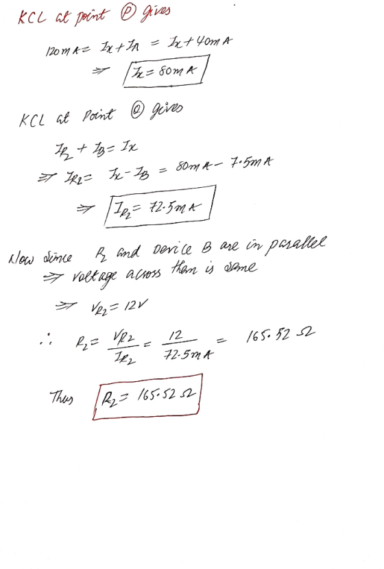
6. [2 marks.] In the circuit below, the 24-Volt source provides 120 mA of current, and...
In the circuit shown below, the voltage source & = 10 volt, R = 500 22,...
 In the circuit shown below, the voltage source & = 10 volt, R = 500 22, R = R, = 1000 . The voltage difference between point a and b Vab=V-V) is: R1 12 13 R & R38 R1 = 500 2 R2 =10002 R3 =1000 2 $=10 V 5 Volt 2 Volt 23 Volt 10 Volt
A student uses the circuit below to measure V characteristic curves for three "unknown" devices (Devices...
 A student uses the circuit below to measure V characteristic curves for three "unknown" devices (Devices 1-3) 120 Q Device Power Supply + The IV graphs are shown below Current (mA) Current (mA) Current (mA) 30 30 30 20- 20 20 10-. 10 10 Voltage (V) 3 Voltage (V) Voltage (V) 3 -1 10/ -2 2 2 -21 2 2 -3 10 10- 20 20 20- 30 30 30 Device 1 Device 2 Device 3 Each "unknown" device could be...
1. In a 24-V DC circuit, the flow of current is measured as 8 A. What...
 1. In a 24-V DC circuit, the flow of current is measured as 8 A. What is the resistance of this circuit? 2. What is the current flow in a 12-V DC simple circuit containing a total resistance of 2 ohms? 3. Determine the current for the 15-V DC circuit shown below. 20Ω 15 VT 4. Determine RT 100 Ω 300 0 RT 200 Ω 125 Ω 5. Determine Rr Ri 6. Determine Rr 20Ω 30 Ω 30 Ω 7....
PROBLEM 4.3 A coil connects to a 120 volt, 50 hertz alternating voltage source; as it's...
 PROBLEM 4.3
A coil connects to a 120 volt, 50 hertz alternating voltage source;
as it's shown in the following. Obtaining the following
readings:
Wattmeter reading = 15 watts
Ammeter Reading = 7.5 Amps
A) Calculate the effective resistance when the coil has a rolled
steel core, if it has a power consumption of 20 watts and a current
of 6 amps
B) Calculate the effective resistance when the coil has a solid
cast iron core, and dissipates a power...
PROBLEM 4.3
A coil connects to a 120 volt, 50 hertz alternating voltage source;
as it's shown in the following. Obtaining the following
readings:
Wattmeter reading = 15 watts
Ammeter Reading = 7.5 Amps
A) Calculate the effective resistance when the coil has a rolled
steel core, if it has a power consumption of 20 watts and a current
of 6 amps
B) Calculate the effective resistance when the coil has a solid
cast iron core, and dissipates a power...
2. For the circuit of Fig. the source is sinusoid of 120 Vrms at a frequency...
 2. For the circuit of Fig. the source is sinusoid of 120 Vrms at a frequency of 60 Hz. The load resistor is 10 12. a) Draw the waveforms of source voltage, output voltage, output current, semiconductor device voltage and semiconductor device current. b) Calculate the average output voltage. c) Calculate the rms output voltage. d) Calculate the average output current. e) Calculate the power absorbed by the resistor. va + vs = Vm sin (@t) R Figure 1: Question...
In an R-L-C series circuit, the magnitude of the phase angle is 40.0o, with the source...
In an R-L-C series circuit, the magnitude of the phase angle is 40.0o, with the source voltage behind the current. The reactance of the capacitor is 300 ohms, and the resistor resistance is 150 ohms. The average power delivered by the source is 120 W. a. What is the reactance of the inductor? b. What is the impedance of the circuit? c. What is the rms current in the circuit? d. What is rms voltage of the source?
PI : For circuit below v-20 V and R,-8 Ohm and R2-2 Ohm. Calculate voltage and...
 PI : For circuit below v-20 V and R,-8 Ohm and R2-2 Ohm. Calculate voltage and power loss in each resistor in the circuit. (Use voltage division and P = (voltage*voltage) resistance)- You cannot use KVL, KCL or Ohms law) Ri R2 P2: For circuit below i = 50 A and R1 = 15 Ohm and R2 = 10 Ohm. Calculate current and power loss in each resistor in the circuit. (Use current division and P - (current*current) resistance) You...
In the circuit shown above, a battery with a voltage ?Vbat = 24 V is connected...
In the circuit shown above, a battery with a voltage ?Vbat = 24 V is connected to the circuit with resistances R1 = 5 Ohms, R2 = 35 Ohms, and R3 = 32 Ohms. The volt meter measures the potential difference between the points A and B, ?VAB. What is the power lost in the resistor R3? Give your answer in Watts to three signficant digits. Do not include units in your answer.
Analyze the following circuit with R1=1.0 kΩ R2=1.2 kΩ : a) Apply ohms law to find...
 Analyze the following circuit with
R1=1.0 kΩ
R2=1.2 kΩ :
a) Apply ohms law to find I3. (Enter answer in mA with 3
decimals)
b) Calculate the power dissipated in R2, Express your answer in
mW with 3 decimals,
c) Apply KCL at node x to determine I2. Enter your answer in mA
with 3 decimals.
d) Calculate the power supplied or absorbed by the voltage
source. Express your answer as a signed mW value to 3 decimals.
e) Apply...
Analyze the following circuit with
R1=1.0 kΩ
R2=1.2 kΩ :
a) Apply ohms law to find I3. (Enter answer in mA with 3
decimals)
b) Calculate the power dissipated in R2, Express your answer in
mW with 3 decimals,
c) Apply KCL at node x to determine I2. Enter your answer in mA
with 3 decimals.
d) Calculate the power supplied or absorbed by the voltage
source. Express your answer as a signed mW value to 3 decimals.
e) Apply...
QUESTION 5 Consider the circuit diagram below. Choose the correct answers about the circuit below. More...
 QUESTION 5 Consider the circuit diagram below. Choose the correct answers about the circuit below. More than one may be correct. R2 = 5760 W R576 w А R = 576 120 V The equivalent resistance of the circuit is 864 Ohms. The voltage across the resistor R1 moving clockwise from the positive side of the battery is equal to the voltage across the parallel combination of R2 and R3, 60 V. The current supplied by the battery is 0.14...
 In the circuit shown below, the voltage source & = 10 volt, R = 500 22, R = R, = 1000 . The voltage difference between point a and b Vab=V-V) is: R1 12 13 R & R38 R1 = 500 2 R2 =10002 R3 =1000 2 $=10 V 5 Volt 2 Volt 23 Volt 10 Volt
 A student uses the circuit below to measure V characteristic curves for three "unknown" devices (Devices 1-3) 120 Q Device Power Supply + The IV graphs are shown below Current (mA) Current (mA) Current (mA) 30 30 30 20- 20 20 10-. 10 10 Voltage (V) 3 Voltage (V) Voltage (V) 3 -1 10/ -2 2 2 -21 2 2 -3 10 10- 20 20 20- 30 30 30 Device 1 Device 2 Device 3 Each "unknown" device could be...
 1. In a 24-V DC circuit, the flow of current is measured as 8 A. What is the resistance of this circuit? 2. What is the current flow in a 12-V DC simple circuit containing a total resistance of 2 ohms? 3. Determine the current for the 15-V DC circuit shown below. 20Ω 15 VT 4. Determine RT 100 Ω 300 0 RT 200 Ω 125 Ω 5. Determine Rr Ri 6. Determine Rr 20Ω 30 Ω 30 Ω 7....
 PROBLEM 4.3
A coil connects to a 120 volt, 50 hertz alternating voltage source;
as it's shown in the following. Obtaining the following
readings:
Wattmeter reading = 15 watts
Ammeter Reading = 7.5 Amps
A) Calculate the effective resistance when the coil has a rolled
steel core, if it has a power consumption of 20 watts and a current
of 6 amps
B) Calculate the effective resistance when the coil has a solid
cast iron core, and dissipates a power...
PROBLEM 4.3
A coil connects to a 120 volt, 50 hertz alternating voltage source;
as it's shown in the following. Obtaining the following
readings:
Wattmeter reading = 15 watts
Ammeter Reading = 7.5 Amps
A) Calculate the effective resistance when the coil has a rolled
steel core, if it has a power consumption of 20 watts and a current
of 6 amps
B) Calculate the effective resistance when the coil has a solid
cast iron core, and dissipates a power...
 2. For the circuit of Fig. the source is sinusoid of 120 Vrms at a frequency of 60 Hz. The load resistor is 10 12. a) Draw the waveforms of source voltage, output voltage, output current, semiconductor device voltage and semiconductor device current. b) Calculate the average output voltage. c) Calculate the rms output voltage. d) Calculate the average output current. e) Calculate the power absorbed by the resistor. va + vs = Vm sin (@t) R Figure 1: Question...
 PI : For circuit below v-20 V and R,-8 Ohm and R2-2 Ohm. Calculate voltage and power loss in each resistor in the circuit. (Use voltage division and P = (voltage*voltage) resistance)- You cannot use KVL, KCL or Ohms law) Ri R2 P2: For circuit below i = 50 A and R1 = 15 Ohm and R2 = 10 Ohm. Calculate current and power loss in each resistor in the circuit. (Use current division and P - (current*current) resistance) You...
 Analyze the following circuit with
R1=1.0 kΩ
R2=1.2 kΩ :
a) Apply ohms law to find I3. (Enter answer in mA with 3
decimals)
b) Calculate the power dissipated in R2, Express your answer in
mW with 3 decimals,
c) Apply KCL at node x to determine I2. Enter your answer in mA
with 3 decimals.
d) Calculate the power supplied or absorbed by the voltage
source. Express your answer as a signed mW value to 3 decimals.
e) Apply...
Analyze the following circuit with
R1=1.0 kΩ
R2=1.2 kΩ :
a) Apply ohms law to find I3. (Enter answer in mA with 3
decimals)
b) Calculate the power dissipated in R2, Express your answer in
mW with 3 decimals,
c) Apply KCL at node x to determine I2. Enter your answer in mA
with 3 decimals.
d) Calculate the power supplied or absorbed by the voltage
source. Express your answer as a signed mW value to 3 decimals.
e) Apply...
 QUESTION 5 Consider the circuit diagram below. Choose the correct answers about the circuit below. More than one may be correct. R2 = 5760 W R576 w А R = 576 120 V The equivalent resistance of the circuit is 864 Ohms. The voltage across the resistor R1 moving clockwise from the positive side of the battery is equal to the voltage across the parallel combination of R2 and R3, 60 V. The current supplied by the battery is 0.14...
Most questions answered within 3 hours.
-
Hello! I was wondering if I could have some help?
If the vapor pressure of carvone...
asked 6 minutes ago -
An economist wants to estimate the mean per capita income (in
thousands of dollars) for a...
asked 26 minutes ago -
What would be the input/output characteristic of a circuit
obtained by putting two of your 2's-complementers...
asked 25 minutes ago -
In Drosophila, the transition from the syncytial blastoderm
stage to the cellular blastoderm stage is a...
asked 53 minutes ago -
Project management question:
Name 3 different types of resources (hint: humans are one
type)
asked 1 hour ago -
Consider the following reaction: C 2H 2( g) + 2H 2( g) C 2H 6(
g)...
asked 1 hour ago -
Consider a 1.0 L buffer containing 0.092 mol L-1 HCOOH and 0.100
mol L-1 HCOO-. What...
asked 1 hour ago -
Koch Realty has owned a vacant land with a FMV of
$775,000 and an adjusted basis...
asked 1 hour ago -
It is estimated 29% of all adults in United States invest in
stocks and that 85%...
asked 1 hour ago -
What does a 2-sided p value of 0.04 mean? (I am not asking if it
is...
asked 1 hour ago -
A parallel-plate capacitor is made from two aluminum-foil
sheets, each 7.8 cmcm wide and 5.1 mmlong....
asked 1 hour ago -
1. why is toluene a stronger nucleophile than benzene?
2.why is phenol a stronger nucleophile than...
asked 2 hours ago