
Homework Answers

Add Answer to:
4- For the electrical system given in the figure: (a) Derive the equations of motion (b)...
(5 marks) For the followving electrical system shown in Figure 3. a) Derive the mathematical mode...
 (5 marks) For the followving electrical system shown in Figure 3. a) Derive the mathematical model of the system b) Draw Block diagram of the system, then, c) Obtain the transfer function of Eo(s)/E (s) Figure 3
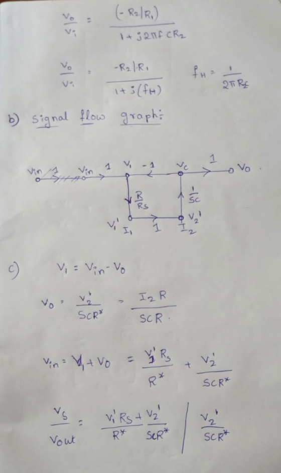
(5 marks) For the followving electrical system shown in Figure 3. a) Derive the mathematical model of the system b) Draw Block diagram of the system, then, c) Obtain the transfer function of Eo(s)/E (s) Figure 3
(5 marks) For the followving electrical system shown in Figure 3. a) Derive the mathematical model of the system b) Draw Block diagram of the system, then, c) Obtain the transfer function of Eo(s)/E (s) Figure 3
Derive the equations of motion of the system shown in the Figure by using Lagrange's equations...
 Derive the equations of motion of the system shown in the Figure by using Lagrange's equations with x and generalized coordinates. Wu
Question: Derive the equations of motion of the trailer compound pendulum system shown in the figure...
 Question: Derive the equations of motion of the trailer compound pendulum system shown in the figure using Lagrange's method. Compound pendulum, mass m, length Trailer, mass M Min)
Question: Derive the equations of motion of the trailer compound pendulum system shown in the figure using Lagrange's method. Compound pendulum, mass m, length Trailer, mass M Min)
Question: Derive the equations of motion of the trailer compound pendulum system shown in the figure using Lagrange's method. Compound pendulum, mass m, length Trailer, mass M Min)
a) [15 marks] Write the differential equations that describe the behavior of the electrical system shown...
 a) [15 marks] Write the differential equations that describe the behavior of the electrical system shown in Figure 1. Assume that all electrical components behave linearly. Note that v(t) is an external input voltage signal, and vi(t) is the output voltage signal, respectively. 0000 1H 1Ω 1Ω M v(t) Figure 1. Electrical network for question 1. Use the currents ij, iz, and iz which flow through the inductors next to the red, green, and blue arrows, respectively, as the key...
Question 4 (10 marks) Using Lagrange's equations to derive the equations of motion for the system...
 Question 4 (10 marks) Using Lagrange's equations to derive the equations of motion for the system shown below. k k m2
The room shown in Figure 1 has a heater with heat flow rate input of q0. The thermal capacitances of the heater and the...
 The room shown in Figure 1 has a heater with heat flow rate
input of q0. The thermal capacitances of the heater and the room
air are C1 and C2, respectively. The thermal resistances of the
heater–air interface and the room wall–ambient air interface are R1
and R2, respectively. The temperatures of the heater and the room
air are T1 and T2, respectively. The temperature outside the room
is T0, which is assumed to be constant.
a. Draw the circuit...
The room shown in Figure 1 has a heater with heat flow rate
input of q0. The thermal capacitances of the heater and the room
air are C1 and C2, respectively. The thermal resistances of the
heater–air interface and the room wall–ambient air interface are R1
and R2, respectively. The temperatures of the heater and the room
air are T1 and T2, respectively. The temperature outside the room
is T0, which is assumed to be constant.
a. Draw the circuit...
4)In large disk drive systems containing linear actuators, the motion is control by a voice-coil ...
 please solve this with detailed description
4)In large disk drive systems containing linear actuators, the motion is control by a voice-coil motor (VCM), as shown in Figure 3. The force F produced is proportional to the current i in the coil. The link between the head (M2) and the servo body (M1) is flexible with spring constant K. Draw a block diagram of the system and obtain the transfer function from input ec to outputy The relevant equations are given...
please solve this with detailed description
4)In large disk drive systems containing linear actuators, the motion is control by a voice-coil motor (VCM), as shown in Figure 3. The force F produced is proportional to the current i in the coil. The link between the head (M2) and the servo body (M1) is flexible with spring constant K. Draw a block diagram of the system and obtain the transfer function from input ec to outputy The relevant equations are given...
the system of equations describing the operation of the ci find the numerical values of the...
 the system of equations describing the operation of the ci find the numerical values of the electrical currents if R,-1 Ω, R2-2 Ω, R,-452, R,-7 Ω, Q-3 Electrical DC circuit is given in Fig, 3. Please: i) Use Kirchhoff's laws and derive rcuit; ii) Solve the system from i) and Ri R2 R3 R4 V2
4. Derive the equations of motion for the shown two degrees system in terms of x...
 4. Derive the equations of motion for the shown two degrees system in terms of x and ?. Bonus 12.5 Pts: Derive and solve the characteristic equation for l = 4 m, m = 3 kg, ki-1 N/m, and k2 = 2 N/m. .
Derive the equation of motion and find the natural frequency of the system shown below (1)...
 Derive the equation of motion and find the natural frequency of the system shown below (1) Cylinder, mass m k R с Pure rolling 1 Αν B I US EE Draw a free body diagram (FBD) with all the forces. Use either Newton's or Lagrange's energy method to derive the equation of motion - Calculate the natural frequency
 (5 marks) For the followving electrical system shown in Figure 3. a) Derive the mathematical model of the system b) Draw Block diagram of the system, then, c) Obtain the transfer function of Eo(s)/E (s) Figure 3
(5 marks) For the followving electrical system shown in Figure 3. a) Derive the mathematical model of the system b) Draw Block diagram of the system, then, c) Obtain the transfer function of Eo(s)/E (s) Figure 3
(5 marks) For the followving electrical system shown in Figure 3. a) Derive the mathematical model of the system b) Draw Block diagram of the system, then, c) Obtain the transfer function of Eo(s)/E (s) Figure 3
 Derive the equations of motion of the system shown in the Figure by using Lagrange's equations with x and generalized coordinates. Wu
 Question: Derive the equations of motion of the trailer compound pendulum system shown in the figure using Lagrange's method. Compound pendulum, mass m, length Trailer, mass M Min)
Question: Derive the equations of motion of the trailer compound pendulum system shown in the figure using Lagrange's method. Compound pendulum, mass m, length Trailer, mass M Min)
Question: Derive the equations of motion of the trailer compound pendulum system shown in the figure using Lagrange's method. Compound pendulum, mass m, length Trailer, mass M Min)
 a) [15 marks] Write the differential equations that describe the behavior of the electrical system shown in Figure 1. Assume that all electrical components behave linearly. Note that v(t) is an external input voltage signal, and vi(t) is the output voltage signal, respectively. 0000 1H 1Ω 1Ω M v(t) Figure 1. Electrical network for question 1. Use the currents ij, iz, and iz which flow through the inductors next to the red, green, and blue arrows, respectively, as the key...
 Question 4 (10 marks) Using Lagrange's equations to derive the equations of motion for the system shown below. k k m2
 The room shown in Figure 1 has a heater with heat flow rate
input of q0. The thermal capacitances of the heater and the room
air are C1 and C2, respectively. The thermal resistances of the
heater–air interface and the room wall–ambient air interface are R1
and R2, respectively. The temperatures of the heater and the room
air are T1 and T2, respectively. The temperature outside the room
is T0, which is assumed to be constant.
a. Draw the circuit...
The room shown in Figure 1 has a heater with heat flow rate
input of q0. The thermal capacitances of the heater and the room
air are C1 and C2, respectively. The thermal resistances of the
heater–air interface and the room wall–ambient air interface are R1
and R2, respectively. The temperatures of the heater and the room
air are T1 and T2, respectively. The temperature outside the room
is T0, which is assumed to be constant.
a. Draw the circuit...
 please solve this with detailed description
4)In large disk drive systems containing linear actuators, the motion is control by a voice-coil motor (VCM), as shown in Figure 3. The force F produced is proportional to the current i in the coil. The link between the head (M2) and the servo body (M1) is flexible with spring constant K. Draw a block diagram of the system and obtain the transfer function from input ec to outputy The relevant equations are given...
please solve this with detailed description
4)In large disk drive systems containing linear actuators, the motion is control by a voice-coil motor (VCM), as shown in Figure 3. The force F produced is proportional to the current i in the coil. The link between the head (M2) and the servo body (M1) is flexible with spring constant K. Draw a block diagram of the system and obtain the transfer function from input ec to outputy The relevant equations are given...
 the system of equations describing the operation of the ci find the numerical values of the electrical currents if R,-1 Ω, R2-2 Ω, R,-452, R,-7 Ω, Q-3 Electrical DC circuit is given in Fig, 3. Please: i) Use Kirchhoff's laws and derive rcuit; ii) Solve the system from i) and Ri R2 R3 R4 V2
 4. Derive the equations of motion for the shown two degrees system in terms of x and ?. Bonus 12.5 Pts: Derive and solve the characteristic equation for l = 4 m, m = 3 kg, ki-1 N/m, and k2 = 2 N/m. .
 Derive the equation of motion and find the natural frequency of the system shown below (1) Cylinder, mass m k R с Pure rolling 1 Αν B I US EE Draw a free body diagram (FBD) with all the forces. Use either Newton's or Lagrange's energy method to derive the equation of motion - Calculate the natural frequency
Most questions answered within 3 hours.
-
Question Three
Suppose you as project manager are using the Waterfall
development methodology on a large...
asked 4 minutes ago -
Which statement is not true about welfare in Canada?
A.Benefits typically vary based on one's ability...
asked 36 minutes ago -
Please help me with FLOWCHART and UML diagram for class,
thank you!
#include <iostream>
#include <fstream>...
asked 1 hour ago -
3. Describe the “logic circuit” of the Lac operon. Which
proteins are bound or not to...
asked 1 hour ago -
Ayesha’s adjusted gross income is $60,000 in 2019. She donated a
piece of artwork with a...
asked 1 hour ago -
For Dijkstra’s shortest path algorithm:
a. Give the Big-O time for Dijkstra’s shortest path algorithm
and...
asked 1 hour ago -
Phosphorus violates the 'octet rule' in biological molecules,
forming more covalent bonds than expected based on...
asked 1 hour ago -
A 1.3 eV electron has a 10-4 probability of tunneling
through a 2.4 eV potential barrier....
asked 2 hours ago -
What is the one ingredient that is common to being successful
with all stakeholders?
profit
trust...
asked 2 hours ago -
Write an assembly language 32 bit program that reads in lines of
text by a .txt...
asked 2 hours ago -
what is the density ( in g/L) of hydrogen gas at 29 degrees C and a...
asked 2 hours ago -
5-6. You are considering three investment alternatives for some
spare cash: Old Reliable Corporation stock (A1),...
asked 2 hours ago