
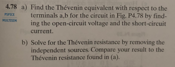
FINAL ANSWER VTH=30 V ; isc=1.5 A; RTH=20 Ω
Homework Answers


Add Answer to:
FINAL ANSWER VTH=30 V ; isc=1.5 A; RTH=20 Ω
Figure P4.78 20 Ω 1.8 A 5Ω...
can you find Voc, Isc, VTH and RTH when V1=minus 5 v , V2=10V , R1=5.1k,...
 can
you find Voc, Isc, VTH and RTH when V1=minus 5 v , V2=10V ,
R1=5.1k, R2=2.2k, R3=3.3k and R4= 6.8k.
R w Figure 8
can
you find Voc, Isc, VTH and RTH when V1=minus 5 v , V2=10V ,
R1=5.1k, R2=2.2k, R3=3.3k and R4= 6.8k.
R w Figure 8
20) Given the circuit shown at right, Calculate VTH and RTH. B) C) D) VTH-10 V,...
 20) Given the circuit shown at right, Calculate VTH and RTH. B) C) D) VTH-10 V, RTH-50 ? Vrh,-6.7 V,Rm,-150 ? VTH,-5.0 V, RTH-50 ? 50? 100 ? 20 VS 100 ? -T 50 ? t ht the Thevenin voltage is
Consider the following figure. (Assume V = 13 V, R1 = 1.8 Ω, and R2 =...
 Consider the following figure.
(Assume V = 13 V, R1 = 1.8 Ω, and R2 = 1.5 Ω.) calculate the
unknown current what's I 1,I 2,I 3
R1 彡↓ Ia 3.0 Ω I9 R2 5.0 Ω
Consider the following figure.
(Assume V = 13 V, R1 = 1.8 Ω, and R2 = 1.5 Ω.) calculate the
unknown current what's I 1,I 2,I 3
R1 彡↓ Ia 3.0 Ω I9 R2 5.0 Ω
0.2500 62 5 + 20 +18 V Given a complex circuit in Figure Q1. This complex...
 0.2500 62 5 + 20 +18 V Given a complex circuit in Figure Q1. This complex circuit is to be viewed in a simpler form of Thevenin and Norton equivalent circuits a) Dengan menggunakan analisis nod, cari voltan Thevenin, Vrh di terminal a dan b. By applying Nodal analysis, find Thevenin voltage, Vru al terminal a and b. (4 markah/marks) b) Sekiranya terminal a dan b dibiarkan bersambung, tentukan nilai semasa arus yang melalui terminal tersebut, iaitu Isc. Berikutan itu,...
10Ω 5Ω sr 2.5mil 20 Ω 12.5 μF Slope/Displacement Find io(t) if Us (t) 35 sin 4000t V. Suppose that i。(t) = 10 cos(wt + φ), where-360° < ф < 360°. Determine the values 10, ω, and φ Express your...
 10Ω 5Ω sr 2.5mil 20 Ω 12.5 μF Slope/Displacement Find io(t) if Us (t) 35 sin 4000t V. Suppose that i。(t) = 10 cos(wt + φ), where-360° < ф < 360°. Determine the values 10, ω, and φ Express your answers using three significant figures separated by commas. View Available Hint(s) ΑΣ A, rad/s, Submit Previous Answers
10Ω 5Ω sr 2.5mil 20 Ω 12.5 μF
Slope/Displacement Find io(t) if Us (t) 35 sin 4000t V. Suppose that i。(t) = 10...
10Ω 5Ω sr 2.5mil 20 Ω 12.5 μF Slope/Displacement Find io(t) if Us (t) 35 sin 4000t V. Suppose that i。(t) = 10 cos(wt + φ), where-360° < ф < 360°. Determine the values 10, ω, and φ Express your answers using three significant figures separated by commas. View Available Hint(s) ΑΣ A, rad/s, Submit Previous Answers
10Ω 5Ω sr 2.5mil 20 Ω 12.5 μF
Slope/Displacement Find io(t) if Us (t) 35 sin 4000t V. Suppose that i。(t) = 10...
Consider the following figure. (Assume V-14 V, R1-2.3 Ω, and R2-1.5 Ω.) Ri 24 V 3.0...
 Consider the following figure. (Assume V-14 V, R1-2.3 Ω, and R2-1.5 Ω.) Ri 24 V 3.0 Ry (a) Can the circuit shown above be reduced to a single resistor connected to the batteries? Explain. No, because different currents flow thru each battery Score: 1 out of Comment: (b) Calculate each of the unknown currents 11, 12. and I3 for the circuit. (Give the magnitude of the current only.) 3.3163X -Your response is within 10% of the correct value. This may...
19. Find the equivalent resistance of the circuit in Figure 1 30 V 18Ω 9.0 Ω...
 19. Find the equivalent resistance of the circuit in Figure 1 30 V 18Ω 9.0 Ω 12Ω 6.0 Ω Figure 1 18.0 Ω 15.0 Ω 12.0 Ω 10.0 Ω C. D. 20. Find the power generated in the circuit in Figure 1 ● 45.0 W . 54.4 W ● 60.0 kW 60.0 W 1. In RC circuits, the discharging behavior is characterized by: a. Exponential growth Exponential decay c. Linear negative decay d. None of the abov In the circuit...
Problem 28.63 Part A What is the current through the 10 Ω resistor in the figure...
 Problem 28.63 Part A What is the current through the 10 Ω resistor in the figure (Figure 1)? Express your answer to two significant figures and include the appropriate units oa Value Units Figure 1 1 of 1 Submit My Answers Give Up Part B Is the current from left to right or right to left? 12V 5Ω left to right right to left 1012 3 V Submit My Answers Give Up Provide Feedback Continue 9 V
Find I1, I2 and I3 for the circuit attached above. 30 Ω 20 V 1 13...
 Find I1, I2 and I3 for the circuit attached above.
30 Ω 20 V 1 13 10 V 112 20 Ω
Find I1, I2 and I3 for the circuit attached above.
30 Ω 20 V 1 13 10 V 112 20 Ω
Please answer with all steps Question II Question In Figure 1, fine V., V and V...
 Please answer with all steps
Question II Question In Figure 1, fine V., V and V In Figure 2, find v 20a 2Ω 1S2 3Ω 32 2 A 322 Figure 1 Figure 2 Question IV Find vi, V2 V and i in Figure 4 Question 11 Fin voltage of all nodes in Figure 3 50Ω 14Ω S0N 75 93 2 A 2:00 Ω 25 Ω 100 Ω 10 Ω BA Figure 4 Figure 3 Question V Find v, and i...
Please answer with all steps
Question II Question In Figure 1, fine V., V and V In Figure 2, find v 20a 2Ω 1S2 3Ω 32 2 A 322 Figure 1 Figure 2 Question IV Find vi, V2 V and i in Figure 4 Question 11 Fin voltage of all nodes in Figure 3 50Ω 14Ω S0N 75 93 2 A 2:00 Ω 25 Ω 100 Ω 10 Ω BA Figure 4 Figure 3 Question V Find v, and i...
 can
you find Voc, Isc, VTH and RTH when V1=minus 5 v , V2=10V ,
R1=5.1k, R2=2.2k, R3=3.3k and R4= 6.8k.
R w Figure 8
can
you find Voc, Isc, VTH and RTH when V1=minus 5 v , V2=10V ,
R1=5.1k, R2=2.2k, R3=3.3k and R4= 6.8k.
R w Figure 8
 20) Given the circuit shown at right, Calculate VTH and RTH. B) C) D) VTH-10 V, RTH-50 ? Vrh,-6.7 V,Rm,-150 ? VTH,-5.0 V, RTH-50 ? 50? 100 ? 20 VS 100 ? -T 50 ? t ht the Thevenin voltage is
 Consider the following figure.
(Assume V = 13 V, R1 = 1.8 Ω, and R2 = 1.5 Ω.) calculate the
unknown current what's I 1,I 2,I 3
R1 彡↓ Ia 3.0 Ω I9 R2 5.0 Ω
Consider the following figure.
(Assume V = 13 V, R1 = 1.8 Ω, and R2 = 1.5 Ω.) calculate the
unknown current what's I 1,I 2,I 3
R1 彡↓ Ia 3.0 Ω I9 R2 5.0 Ω
 0.2500 62 5 + 20 +18 V Given a complex circuit in Figure Q1. This complex circuit is to be viewed in a simpler form of Thevenin and Norton equivalent circuits a) Dengan menggunakan analisis nod, cari voltan Thevenin, Vrh di terminal a dan b. By applying Nodal analysis, find Thevenin voltage, Vru al terminal a and b. (4 markah/marks) b) Sekiranya terminal a dan b dibiarkan bersambung, tentukan nilai semasa arus yang melalui terminal tersebut, iaitu Isc. Berikutan itu,...
 10Ω 5Ω sr 2.5mil 20 Ω 12.5 μF Slope/Displacement Find io(t) if Us (t) 35 sin 4000t V. Suppose that i。(t) = 10 cos(wt + φ), where-360° < ф < 360°. Determine the values 10, ω, and φ Express your answers using three significant figures separated by commas. View Available Hint(s) ΑΣ A, rad/s, Submit Previous Answers
10Ω 5Ω sr 2.5mil 20 Ω 12.5 μF
Slope/Displacement Find io(t) if Us (t) 35 sin 4000t V. Suppose that i。(t) = 10...
10Ω 5Ω sr 2.5mil 20 Ω 12.5 μF Slope/Displacement Find io(t) if Us (t) 35 sin 4000t V. Suppose that i。(t) = 10 cos(wt + φ), where-360° < ф < 360°. Determine the values 10, ω, and φ Express your answers using three significant figures separated by commas. View Available Hint(s) ΑΣ A, rad/s, Submit Previous Answers
10Ω 5Ω sr 2.5mil 20 Ω 12.5 μF
Slope/Displacement Find io(t) if Us (t) 35 sin 4000t V. Suppose that i。(t) = 10...
 Consider the following figure. (Assume V-14 V, R1-2.3 Ω, and R2-1.5 Ω.) Ri 24 V 3.0 Ry (a) Can the circuit shown above be reduced to a single resistor connected to the batteries? Explain. No, because different currents flow thru each battery Score: 1 out of Comment: (b) Calculate each of the unknown currents 11, 12. and I3 for the circuit. (Give the magnitude of the current only.) 3.3163X -Your response is within 10% of the correct value. This may...
 19. Find the equivalent resistance of the circuit in Figure 1 30 V 18Ω 9.0 Ω 12Ω 6.0 Ω Figure 1 18.0 Ω 15.0 Ω 12.0 Ω 10.0 Ω C. D. 20. Find the power generated in the circuit in Figure 1 ● 45.0 W . 54.4 W ● 60.0 kW 60.0 W 1. In RC circuits, the discharging behavior is characterized by: a. Exponential growth Exponential decay c. Linear negative decay d. None of the abov In the circuit...
 Problem 28.63 Part A What is the current through the 10 Ω resistor in the figure (Figure 1)? Express your answer to two significant figures and include the appropriate units oa Value Units Figure 1 1 of 1 Submit My Answers Give Up Part B Is the current from left to right or right to left? 12V 5Ω left to right right to left 1012 3 V Submit My Answers Give Up Provide Feedback Continue 9 V
 Find I1, I2 and I3 for the circuit attached above.
30 Ω 20 V 1 13 10 V 112 20 Ω
Find I1, I2 and I3 for the circuit attached above.
30 Ω 20 V 1 13 10 V 112 20 Ω
 Please answer with all steps
Question II Question In Figure 1, fine V., V and V In Figure 2, find v 20a 2Ω 1S2 3Ω 32 2 A 322 Figure 1 Figure 2 Question IV Find vi, V2 V and i in Figure 4 Question 11 Fin voltage of all nodes in Figure 3 50Ω 14Ω S0N 75 93 2 A 2:00 Ω 25 Ω 100 Ω 10 Ω BA Figure 4 Figure 3 Question V Find v, and i...
Please answer with all steps
Question II Question In Figure 1, fine V., V and V In Figure 2, find v 20a 2Ω 1S2 3Ω 32 2 A 322 Figure 1 Figure 2 Question IV Find vi, V2 V and i in Figure 4 Question 11 Fin voltage of all nodes in Figure 3 50Ω 14Ω S0N 75 93 2 A 2:00 Ω 25 Ω 100 Ω 10 Ω BA Figure 4 Figure 3 Question V Find v, and i...
Most questions answered within 3 hours.
-
Under all the various types of market structures, firms
must eventually earn some economic profits for...
asked 4 minutes ago -
Consider the following fitness regime for a single locus trait
with two co-dominant alleles: w11 =...
asked 9 minutes ago -
A large cable company reports the following.
80% of its customers subscribe to its cable TV...
asked 24 minutes ago -
Please answer the question in brief.
Discuss the role of ERP in organizations. Are ERP tools...
asked 10 minutes ago -
Discuss the pros and cons of collaborative software such
as SameTime. Does it increase productivity? What...
asked 22 minutes ago -
1. Are all good samples random?
2. Magazines often report surveys giving statistics such as “63%...
asked 17 minutes ago -
Buying your in-laws a gift because it’s expected is
due to the ____________ motive of gift-giving....
asked 25 minutes ago -
Calculate the expected value, the variance, and the standard
deviation of the given random variable X....
asked 1 hour ago -
A hospital performs 100 surgeries per week. The probability that
complications after surgery occur is 10%....
asked 1 hour ago -
1 point) Given the significance level α=0.01 find the following:
(a) left-tailed z value z= (b)...
asked 1 hour ago -
Assuming you are the head of the software development unit at
Cyber.Soft, explain and justify why...
asked 33 minutes ago -
Magnesium and nitrogen react in a combination reaction to
produce magnesium nitride. 3 Mg + N2...
asked 41 minutes ago