
Homework Answers


Add Answer to:
Part A Consider the truss shown in (Figure 1). Assume the members are pin connected at...
Review Consider the truss shown in (Fiqure 1). Assume all members are pin connected. Suppose that...
 Review Consider the truss shown in (Fiqure 1). Assume all members are pin connected. Suppose that P = 4.2 k Figure <,1 of 1 F 4 k F. Go E 15 ft H 6 ft D B AL 10 ft -10 ft 15 ft 15 ft Part B Determine the force in member BC. State if the member is in tension or compression. Express your answer using three significant figures. Enter positive value in the case of tension and negative...
Problem 3.21 6of7 Review Part A Consider the truss shown in (Figure 1) Suppose that F-8 k.Assume all members are pin...
 Problem 3.21 6of7 Review Part A Consider the truss shown in (Figure 1) Suppose that F-8 k.Assume all members are pin connected Determine the force in the member FC of the truss and state if the member is in tension or compression. Express your answer using three significant figures. Enter negative value in the case of compression and positive value in the case of tension. Figure 1 of 1 1.5 k Frc 3.04 6 ft Submit wers Request An 6...
a. Specify the type of compound truss shown in Figure 2. Assume all members are pin...
 a. Specify the type of compound truss shown in Figure 2. Assume all members are pin connected. The truss is pin supported at A and roller supported at F. Investigate the determinacy and stability of the truss Using the method of section, determine the force in member CD. State if the member is in b. c. tension or compression d. Using the method of joint, determine the force in members JK and JN. State if the members are in tension...
Problem 8.49 Item 7 I Review Consider the L-shaped frame shown in (Figure 1). There is...
 Problem 8.49 Item 7 I Review Consider the L-shaped frame shown in (Figure 1). There is a fixed support at A and fixed joint at B. El is constant Assume w = 220 lb/ft, and El is measured in lb. ft”, Part B Use the method of virtual work and determine the horizontal displacement of point C measured leftward. Express your answer using three significant figures. Enter positive value if the displacement is leftward and negative value if the displacement...
Part A Consider the structure shown in (Figure 1). Assume the members are pin-connected at A,...
 Part A Consider the structure shown in (Figure 1). Assume the members are pin-connected at A, B, and C. Suppose that P = 7.5 kN. Determine the horizontal component of reaction at the support A. Express your answer to three significant figures and include the appropriate units - Tuà • • • Ea ? A - Value Units Submit Request Answer Figure 1 of 1 > Part B Determine the vertical component of reaction at the support A. Express your...
3. The members of a truss are pin connected at joint O, as shown in Figure...
 3. The members of a truss are pin connected at joint O, as shown in Figure 3. Determine the magnitude of Fy and its angle for equilibrium. Given that F2 = 6 kN. 5 kN E 60 30 . 7 kN Figure 3
1 Review Part A Consider the truss shown in (Figure 1). Assume the diagonals can support...
 1 Review Part A Consider the truss shown in (Figure 1). Assume the diagonals can support either a tensile or a compressive force. Suppose that P = 4k P2 = 6 k, P3 = 5 k. Determine (approximately) the force in member CD of the truss. State if the member is in tension or compression. Express your answer using three significant figures. Enter negative value in the case of compression and positive value in the case of tension. O AEQ...
P17.092 Incorrect Compute the vertical displacement Δο of joint D for the truss in the figure....
 P17.092 Incorrect Compute the vertical displacement Δο of joint D for the truss in the figure. Assume that each member has a cross sectional area of A 15s in 2 and an elastic modul ofE-30 500 ksi The loads acting on the truss are P 18 kips and Q 31 kips. Employ Castigliano's second theorem. The vertical displacement Δο is positive if upward and negative if downward. Assume that a-23 ft, b = 10ft,and c = 23 ft. よ L....
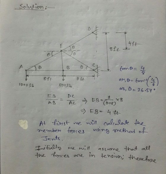
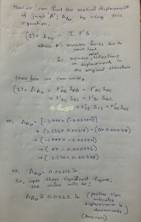
Consider the truss shown in (Figure 1). AE is constant. Take L = 8.5 ft. Part...
 Consider the truss shown in (Figure 1). AE is constant. Take L = 8.5 ft. Part A Determine the force in the member AC of the truss. State if the member is in tension or compression Express your answer using three significant figures. Enter negative value in the case of compression and positive value in the case of tension. ΟΙ ΑΣφTIf | vec ? k Submit Request Answer Provide Feedback Figure < 1 of 1 611 61 B 6K 6k
HWK #16 Problem 9.26 3 of 3 Consider the cantilever beam shown in (Figure 1). Take...
 HWK #16 Problem 9.26 3 of 3 Consider the cantilever beam shown in (Figure 1). Take E- 29(103) ksi, IAB 400 in., and IC 200 in.4 Use the principle of virtual work. Part A Determine the displacement at point C of the cantilever beam measured downward Express your answer using three significant figures. Enter positive value if the displacement is downward and negative value if the displacement is upward. Ac: 0.509 in. Figure < 1of1 > Submit vious Ans uest...
 Review Consider the truss shown in (Fiqure 1). Assume all members are pin connected. Suppose that P = 4.2 k Figure <,1 of 1 F 4 k F. Go E 15 ft H 6 ft D B AL 10 ft -10 ft 15 ft 15 ft Part B Determine the force in member BC. State if the member is in tension or compression. Express your answer using three significant figures. Enter positive value in the case of tension and negative...
 Problem 3.21 6of7 Review Part A Consider the truss shown in (Figure 1) Suppose that F-8 k.Assume all members are pin connected Determine the force in the member FC of the truss and state if the member is in tension or compression. Express your answer using three significant figures. Enter negative value in the case of compression and positive value in the case of tension. Figure 1 of 1 1.5 k Frc 3.04 6 ft Submit wers Request An 6...
 a. Specify the type of compound truss shown in Figure 2. Assume all members are pin connected. The truss is pin supported at A and roller supported at F. Investigate the determinacy and stability of the truss Using the method of section, determine the force in member CD. State if the member is in b. c. tension or compression d. Using the method of joint, determine the force in members JK and JN. State if the members are in tension...
 Problem 8.49 Item 7 I Review Consider the L-shaped frame shown in (Figure 1). There is a fixed support at A and fixed joint at B. El is constant Assume w = 220 lb/ft, and El is measured in lb. ft”, Part B Use the method of virtual work and determine the horizontal displacement of point C measured leftward. Express your answer using three significant figures. Enter positive value if the displacement is leftward and negative value if the displacement...
 Part A Consider the structure shown in (Figure 1). Assume the members are pin-connected at A, B, and C. Suppose that P = 7.5 kN. Determine the horizontal component of reaction at the support A. Express your answer to three significant figures and include the appropriate units - Tuà • • • Ea ? A - Value Units Submit Request Answer Figure 1 of 1 > Part B Determine the vertical component of reaction at the support A. Express your...
 3. The members of a truss are pin connected at joint O, as shown in Figure 3. Determine the magnitude of Fy and its angle for equilibrium. Given that F2 = 6 kN. 5 kN E 60 30 . 7 kN Figure 3
 1 Review Part A Consider the truss shown in (Figure 1). Assume the diagonals can support either a tensile or a compressive force. Suppose that P = 4k P2 = 6 k, P3 = 5 k. Determine (approximately) the force in member CD of the truss. State if the member is in tension or compression. Express your answer using three significant figures. Enter negative value in the case of compression and positive value in the case of tension. O AEQ...
 P17.092 Incorrect Compute the vertical displacement Δο of joint D for the truss in the figure. Assume that each member has a cross sectional area of A 15s in 2 and an elastic modul ofE-30 500 ksi The loads acting on the truss are P 18 kips and Q 31 kips. Employ Castigliano's second theorem. The vertical displacement Δο is positive if upward and negative if downward. Assume that a-23 ft, b = 10ft,and c = 23 ft. よ L....
 Consider the truss shown in (Figure 1). AE is constant. Take L = 8.5 ft. Part A Determine the force in the member AC of the truss. State if the member is in tension or compression Express your answer using three significant figures. Enter negative value in the case of compression and positive value in the case of tension. ΟΙ ΑΣφTIf | vec ? k Submit Request Answer Provide Feedback Figure < 1 of 1 611 61 B 6K 6k
 HWK #16 Problem 9.26 3 of 3 Consider the cantilever beam shown in (Figure 1). Take E- 29(103) ksi, IAB 400 in., and IC 200 in.4 Use the principle of virtual work. Part A Determine the displacement at point C of the cantilever beam measured downward Express your answer using three significant figures. Enter positive value if the displacement is downward and negative value if the displacement is upward. Ac: 0.509 in. Figure < 1of1 > Submit vious Ans uest...
Most questions answered within 3 hours.
-
Write a program to solve the Josephus problem, with the following
modification:
Sample Input:
./a.out n...
asked 52 minutes ago -
At the start of a CD it is spinning at a rate of 525 rpm
(revolutions...
asked 1 hour ago -
4. Without doing any calculations, predict whether the observed
∆T would increase, decrease or remain the...
asked 2 hours ago -
Based on the range, which of the following sets of scores has
the greatest variability? 3,...
asked 3 hours ago -
Ripples in a pond travel at a velocity of 3 m/s with one peak
passing a...
asked 3 hours ago -
A man stands on the roof of a building of height 13.0 mm and
throws a...
asked 3 hours ago -
The extent to which assets are financed by borrowed funds and
other liabilities is indicated by:...
asked 4 hours ago -
Explain in detail
Germany is the fifth largest economy
explain what goods and services Germany specializes...
asked 5 hours ago -
The density of platinum is 21.45 g/mL. If a cube of platinum
with a mass of...
asked 5 hours ago -
Accounts Receivable
Sales
A/R Posting
Extended Sales Invoice
Packing Slip
Compare invoice to packing slip 2...
asked 5 hours ago -
Michaella, age 23, is a full-time law student and is claimed by
her parents as a...
asked 5 hours ago -
Why are polymers not typically casted into products?
asked 5 hours ago