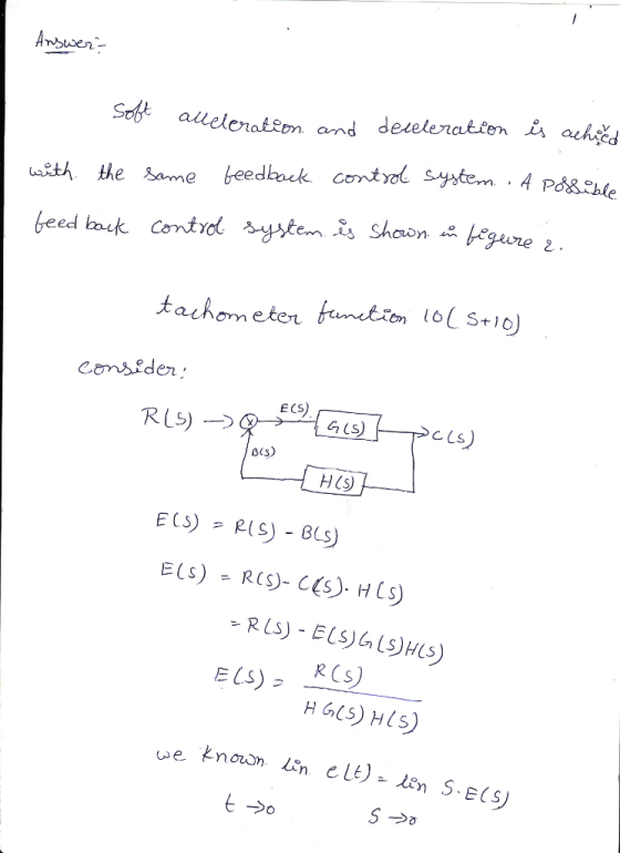
![Elevator motors require feedback control to avoid speed differences between up- ward and downward movement and when a different number of passengers ride the elevator car. Soft acceleration and deceleration is achieved with the same feedback control system. A possible feedback control system is shown in Figure 2. E(s) Motor R(S) H(S) w(S) S+5 10 S+10 Figure 2: motor. Suggested feedback control system for controlling the speed ?(s) of an elevator The motor speed is measured with an optical encoder, and the integration of the encoder slits causes a slightly delayed response that can be modeled with the tachometer function 10/(s10). To simplify the task, the steady-state gain of the motor is combined with the controller, and we can describe a PI controller with the transfer function s + where g is an adjustable gain parameter and k is the adjustable weight coefficient of the integral component. A. Formally prove that the steady-state tracking error vanishes in this feedback configuration when kl > 0 and the input R(s) Is bounded. Hint: The tracking error E(s) is defined as E(s)R(s)-s. It is sufficient to show with the final value theorem that ?(t ? oo) = R(1 ? ?), irrespective of the actual function R(s). If you insist, you may use R(s) 1/s. [5 points]](http://img.homeworklib.com/questions/ef28e000-c720-11ea-8e13-57cc997d3a06.png?x-oss-process=image/resize,w_560)
Homework Answers


Add Answer to:
Elevator motors require feedback control to avoid speed differences between up- ward and downward movement and...
A unity feedback closed loop control system is displayed in Figure 4. (a) Assume that the control...
 Please solve as a MATLAB code.
A unity feedback closed loop control system is displayed in Figure 4. (a) Assume that the controller is given by G (s) 2. Based on the lsim function of MATLAB, calculate and obtain the graph of the response for (t) at. Here a 0.5°/s. Find the height error after 10 seconds, (b) In order to reduce the steady-state error, substitute G (s) with the following controller This is a Proportional-Integral (PI) controller. Repeat part...
Please solve as a MATLAB code.
A unity feedback closed loop control system is displayed in Figure 4. (a) Assume that the controller is given by G (s) 2. Based on the lsim function of MATLAB, calculate and obtain the graph of the response for (t) at. Here a 0.5°/s. Find the height error after 10 seconds, (b) In order to reduce the steady-state error, substitute G (s) with the following controller This is a Proportional-Integral (PI) controller. Repeat part...
6 and controller C(s), as shown in the Consider a unity-feedback control system with plant G(s)-...
 6 and controller C(s), as shown in the Consider a unity-feedback control system with plant G(s)- following figure. Reference Error Controller Plant r(t) e(t) u(t) y(t) C(s) G(s) [5] (a) Determine the poles, zeros, order, type, relative degree, and de gain of the plant G(s) and show [5] (b) Can a P controller C(s)Kp stabilize the plant G(s)? If so, find the values of Kp that are [4] (c) Show using the Final Value Theorem that the system with the...
Problem 51: (25 points) Figure 5 is an example of a feedback control system that is designed to r...
 Problem 51: (25 points) Figure 5 is an example of a feedback control system that is designed to regulate the angular position θ(t) of a motor shaft to a desired value θr(t). The signal e(t) represents the error between the measured shaft angle θ(t) and the desired shaft angle θ (t). The Laplace transforms ofa,(t), θ(t), and e(t) are denoted as ΘR(s), θ(s), and E(s), respectively. The control gains Ki and K2 are chosen by the control engineer to achieve...
Suppose we are given a unit feedback system where the plant transfer function is given as...
 Suppose we are given a unit feedback system where the plant transfer function is given as 4 G(S) +2 the reference signal x ()-A cos(), and the disturbance signal as a step function dt) Cu. Use the internal model principle to design the feedback control transfer function K(s) such that the steady-state tracking error e r-y is independent of the reference and disturbance signals
Consider the electro-mechanical feedback control system shown in Figure 3. The voltage Ea(s) - Liea(t)) is...
 Consider the electro-mechanical feedback control system shown in Figure 3. The voltage Ea(s) - Liea(t)) is generated by an amplifier whose transfer function is Ga(s) -5 The position sensor has a transfer function H(s) 1 and the pre-compensator transfer function is pot X (s) Ea(s) The "Electro-Mechanical System" block, is X(s) Ea(s) 5.05s3 101s2 +505.2s 100 R(s) Amplifier, |Ea(S)Electro-MechanicalX(S) Controller, Gc(s) K, pot Ga(s) System, G(s) Encoder H(s) Figure 3: Electro-mechanical control system for Question 3 Consider a proportional controller...
5. Consider the feedback control system shown below with constant reference w, and constant disturbance d....
 5. Consider the feedback control system shown below with constant reference w, and constant disturbance d. Show that the steady-state error e(0o) lm()is zero when k>0 and is given by (wr +Kd)/(Kkp +1) when k0 Lu TS+ Figure 1: Speed regulation of DC motor using PI controller
PLEASE DO IN MATLAB Problem 8 (PID feedback control). This problem is about Proportional-Integral-Derivative feedback control...
 PLEASE DO IN MATLAB
Problem 8 (PID feedback control). This problem is about Proportional-Integral-Derivative feedback control systems. The general setup of the system we are going to look at is given below: e(t) u(t) |C(s) y(t) P(s) r(t) Here the various signals are: signal/system r(t) y(t) e(t) P(s) C(s) и(t) meaning desired output signal actual output signal error signal r(t) y(t) Laplace transform of the (unstable) plant controller to be designed control signal Our goal is to design a controller...
PLEASE DO IN MATLAB
Problem 8 (PID feedback control). This problem is about Proportional-Integral-Derivative feedback control systems. The general setup of the system we are going to look at is given below: e(t) u(t) |C(s) y(t) P(s) r(t) Here the various signals are: signal/system r(t) y(t) e(t) P(s) C(s) и(t) meaning desired output signal actual output signal error signal r(t) y(t) Laplace transform of the (unstable) plant controller to be designed control signal Our goal is to design a controller...
G) r(t) Figure 1: Feedback control system A pulley and belt transmission has a linearized relationship between the driven pulley angle θ(t) in degrees and the input torque u(t) in Newton meters given...
 G) r(t) Figure 1: Feedback control system A pulley and belt transmission has a linearized relationship between the driven pulley angle θ(t) in degrees and the input torque u(t) in Newton meters given by the following differential equation du(t) A feedback control system (illustrated in Figure 1) needs to be designed such that the closed-loop system is asymptotically stable and such that the following design criteria are met: 1. the gain crossover frequency a should be between and a 2....
Consider a two-tank system, where x, is the level of the first tank, and x2 is the level of the second tank. This dynamic system is described by the -xj-x2. The output to be Q4. following model: dt c...
 Consider a two-tank system, where x, is the level of the first tank, and x2 is the level of the second tank. This dynamic system is described by the -xj-x2. The output to be Q4. following model: dt controlled is the level of the second tank. (a)Write down the state-space model in matrix form. Verify the 20% (b)Design a state feedback controller so that the closed-loop poles are 25% controllability of the system located at -3 and -4 (c) The...
P4: The car model of a cruise control system is given in the following transfer function...
 P4: The car model of a cruise control system is given in the following transfer function block diagram ms + b Where v is the car speed u is the control force m is the mass of the vehicle, 1000 kg b is the damping coefficient, 50 N s/m More details are available here (1) Derive the differential equation relating y(t) to u(t) (2) Determine the time constant of the car dynamics (from u to v) If a proportional feedback...
 Please solve as a MATLAB code.
A unity feedback closed loop control system is displayed in Figure 4. (a) Assume that the controller is given by G (s) 2. Based on the lsim function of MATLAB, calculate and obtain the graph of the response for (t) at. Here a 0.5°/s. Find the height error after 10 seconds, (b) In order to reduce the steady-state error, substitute G (s) with the following controller This is a Proportional-Integral (PI) controller. Repeat part...
Please solve as a MATLAB code.
A unity feedback closed loop control system is displayed in Figure 4. (a) Assume that the controller is given by G (s) 2. Based on the lsim function of MATLAB, calculate and obtain the graph of the response for (t) at. Here a 0.5°/s. Find the height error after 10 seconds, (b) In order to reduce the steady-state error, substitute G (s) with the following controller This is a Proportional-Integral (PI) controller. Repeat part...
 6 and controller C(s), as shown in the Consider a unity-feedback control system with plant G(s)- following figure. Reference Error Controller Plant r(t) e(t) u(t) y(t) C(s) G(s) [5] (a) Determine the poles, zeros, order, type, relative degree, and de gain of the plant G(s) and show [5] (b) Can a P controller C(s)Kp stabilize the plant G(s)? If so, find the values of Kp that are [4] (c) Show using the Final Value Theorem that the system with the...
 Problem 51: (25 points) Figure 5 is an example of a feedback control system that is designed to regulate the angular position θ(t) of a motor shaft to a desired value θr(t). The signal e(t) represents the error between the measured shaft angle θ(t) and the desired shaft angle θ (t). The Laplace transforms ofa,(t), θ(t), and e(t) are denoted as ΘR(s), θ(s), and E(s), respectively. The control gains Ki and K2 are chosen by the control engineer to achieve...
 Suppose we are given a unit feedback system where the plant transfer function is given as 4 G(S) +2 the reference signal x ()-A cos(), and the disturbance signal as a step function dt) Cu. Use the internal model principle to design the feedback control transfer function K(s) such that the steady-state tracking error e r-y is independent of the reference and disturbance signals
 Consider the electro-mechanical feedback control system shown in Figure 3. The voltage Ea(s) - Liea(t)) is generated by an amplifier whose transfer function is Ga(s) -5 The position sensor has a transfer function H(s) 1 and the pre-compensator transfer function is pot X (s) Ea(s) The "Electro-Mechanical System" block, is X(s) Ea(s) 5.05s3 101s2 +505.2s 100 R(s) Amplifier, |Ea(S)Electro-MechanicalX(S) Controller, Gc(s) K, pot Ga(s) System, G(s) Encoder H(s) Figure 3: Electro-mechanical control system for Question 3 Consider a proportional controller...
 5. Consider the feedback control system shown below with constant reference w, and constant disturbance d. Show that the steady-state error e(0o) lm()is zero when k>0 and is given by (wr +Kd)/(Kkp +1) when k0 Lu TS+ Figure 1: Speed regulation of DC motor using PI controller
 PLEASE DO IN MATLAB
Problem 8 (PID feedback control). This problem is about Proportional-Integral-Derivative feedback control systems. The general setup of the system we are going to look at is given below: e(t) u(t) |C(s) y(t) P(s) r(t) Here the various signals are: signal/system r(t) y(t) e(t) P(s) C(s) и(t) meaning desired output signal actual output signal error signal r(t) y(t) Laplace transform of the (unstable) plant controller to be designed control signal Our goal is to design a controller...
PLEASE DO IN MATLAB
Problem 8 (PID feedback control). This problem is about Proportional-Integral-Derivative feedback control systems. The general setup of the system we are going to look at is given below: e(t) u(t) |C(s) y(t) P(s) r(t) Here the various signals are: signal/system r(t) y(t) e(t) P(s) C(s) и(t) meaning desired output signal actual output signal error signal r(t) y(t) Laplace transform of the (unstable) plant controller to be designed control signal Our goal is to design a controller...
 G) r(t) Figure 1: Feedback control system A pulley and belt transmission has a linearized relationship between the driven pulley angle θ(t) in degrees and the input torque u(t) in Newton meters given by the following differential equation du(t) A feedback control system (illustrated in Figure 1) needs to be designed such that the closed-loop system is asymptotically stable and such that the following design criteria are met: 1. the gain crossover frequency a should be between and a 2....
 Consider a two-tank system, where x, is the level of the first tank, and x2 is the level of the second tank. This dynamic system is described by the -xj-x2. The output to be Q4. following model: dt controlled is the level of the second tank. (a)Write down the state-space model in matrix form. Verify the 20% (b)Design a state feedback controller so that the closed-loop poles are 25% controllability of the system located at -3 and -4 (c) The...
 P4: The car model of a cruise control system is given in the following transfer function block diagram ms + b Where v is the car speed u is the control force m is the mass of the vehicle, 1000 kg b is the damping coefficient, 50 N s/m More details are available here (1) Derive the differential equation relating y(t) to u(t) (2) Determine the time constant of the car dynamics (from u to v) If a proportional feedback...
Most questions answered within 3 hours.
-
Calculate the approximate number of residues of Rubisco, which
is involved in carbon fixation in plants,...
asked 2 minutes ago -
Other decisions about scientific claims can have a much broader
impact.ENERGYarrow-10x10.png, environment, health, security - all...
asked 57 minutes ago -
I need to write a research paper and work cited about this
topic: The United States...
asked 1 hour ago -
Hello! I was wondering if I could have some help?
If the vapor pressure of carvone...
asked 1 hour ago -
An economist wants to estimate the mean per capita income (in
thousands of dollars) for a...
asked 2 hours ago -
What would be the input/output characteristic of a circuit
obtained by putting two of your 2's-complementers...
asked 1 hour ago -
In Drosophila, the transition from the syncytial blastoderm
stage to the cellular blastoderm stage is a...
asked 2 hours ago -
Project management question:
Name 3 different types of resources (hint: humans are one
type)
asked 2 hours ago -
Consider the following reaction: C 2H 2( g) + 2H 2( g) C 2H 6(
g)...
asked 2 hours ago -
Consider a 1.0 L buffer containing 0.092 mol L-1 HCOOH and 0.100
mol L-1 HCOO-. What...
asked 2 hours ago -
Koch Realty has owned a vacant land with a FMV of
$775,000 and an adjusted basis...
asked 3 hours ago -
It is estimated 29% of all adults in United States invest in
stocks and that 85%...
asked 3 hours ago