Can someone please solve the below lab in MATLAB showing the code and the output result as well please? Me and my partners cannot get our codes to give us the outputs.

Homework Answers


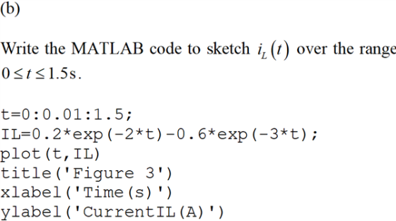
![CurrentIL(A) Time(s) Figure 3 (c) Given, L=1H. Calculate the energy stored in the inductor. E. ()=52,(1) =(1)[0.287 -0.6e] =](http://img.homeworklib.com/questions/503072d0-ca19-11ea-9a47-b34a294fc077.png?x-oss-process=image/resize,w_560)

Add Answer to:
Can someone please solve the below lab in MATLAB showing the
code and the output result...
SOLVE BY USING MATLAB 6. For the sequential circuit shown in Figure, the current flowing through...
 SOLVE BY USING MATLAB
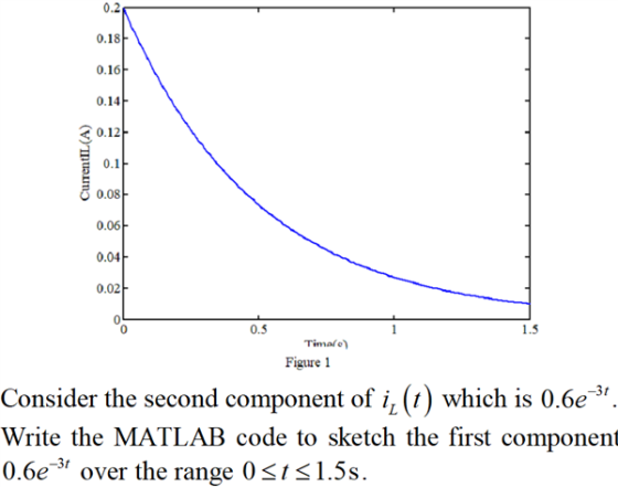
6. For the sequential circuit shown in Figure, the current flowing through the inductor is zero. At t = 0, the switch moved from position a to b, where it remained for 1 s. After the 1 s delay, the switch moved from position b to position c, where it remained indefinitely. Sketch (plot) the current flowing through the inductor versus time. 50 Ohms / 200 H mm M + 40V 150 Ohms 350 Ohms 1
SOLVE BY USING MATLAB
6. For the sequential circuit shown in Figure, the current flowing through the inductor is zero. At t = 0, the switch moved from position a to b, where it remained for 1 s. After the 1 s delay, the switch moved from position b to position c, where it remained indefinitely. Sketch (plot) the current flowing through the inductor versus time. 50 Ohms / 200 H mm M + 40V 150 Ohms 350 Ohms 1
MATLAB WORK PLEASE An oscillating current in an electric circuit is given by: I = 9e-t...
 MATLAB WORK PLEASE
An oscillating current in an electric circuit is given by: I = 9e-t sin(2nt) where I is the current in Amperes and t is the time in seconds. Use fzero to determine the two values of t in the range of 0 <t< 1.5 such that I desired = -1.15A. (What does a negative current physically mean?) The outputs of the function are t, and t2, where tı = first time that I desired = -1.15A and...
MATLAB WORK PLEASE
An oscillating current in an electric circuit is given by: I = 9e-t sin(2nt) where I is the current in Amperes and t is the time in seconds. Use fzero to determine the two values of t in the range of 0 <t< 1.5 such that I desired = -1.15A. (What does a negative current physically mean?) The outputs of the function are t, and t2, where tı = first time that I desired = -1.15A and...
please do this problem in matlab and show me the code. Thanks. please do this problem...
 please do this problem in matlab and show me the code.
Thanks.
please do this problem in matlab and show me the code.
Thanks.
please do this problem in matlab and show me the code.
Thanks.
please do this problem in matlab and show me the code.
Thanks.
please do this problem in matlab and show me the code.
Thanks.please do this problem in matlab
and show me the code. Thanks.
please do this problem in matlab and show me...
please do this problem in matlab and show me the code.
Thanks.
please do this problem in matlab and show me the code.
Thanks.
please do this problem in matlab and show me the code.
Thanks.
please do this problem in matlab and show me the code.
Thanks.
please do this problem in matlab and show me the code.
Thanks.please do this problem in matlab
and show me the code. Thanks.
please do this problem in matlab and show me...
Please help me write a code for this in Matlab T = 1 millisecond Vm =...
Please help me write a code for this in Matlab T = 1 millisecond Vm = 1 volt (amplitude voltage) t = linspace(-T, 2*T, 3001) The following pararameter is given v(t) = Vm - (Vm/T)t for 0<= t <= T 0 elsewhere I need to modify the vector v so that is represents a periodic function with a period T over this time period (hint: it should look like a sawtooth), and plot v vs t over the range from...
Please write and include a matlab code for the following: Given the following differential equation 10?̈+...
 Please write and include a matlab code for the
following:
Given the following differential equation
10?̈+ 20?̇ + 250? = ?(?)
a. Plot response to f(t) = 200sin(4t)
b. Plot response to a step f(t) = 200 that starts at t = 0 s and
stops at t = 2s; note that the
response goes past the 2 seconds of input.
Part a.) I need matlab code to generate the plot for
10x''+20x'+250x=200sin(4t)
Part b.) I need matlab code to...
Please write and include a matlab code for the
following:
Given the following differential equation
10?̈+ 20?̇ + 250? = ?(?)
a. Plot response to f(t) = 200sin(4t)
b. Plot response to a step f(t) = 200 that starts at t = 0 s and
stops at t = 2s; note that the
response goes past the 2 seconds of input.
Part a.) I need matlab code to generate the plot for
10x''+20x'+250x=200sin(4t)
Part b.) I need matlab code to...
can you show how the model would look like on matlab ? please help with this question For the circuit given below, find the normal form for the inductor current and capacitor voltage. Use Matlab (...
 can you show how the model would look like on matlab ? please
help with this question
For the circuit given below, find the normal form for the inductor current and capacitor voltage. Use Matlab (Create an.m file. Use Isim function) and Simulink (Create a Simulink Model). Plot the responses x1 and x2 over time from the M file and Simulink Model. Do they match? Please explain. Use f(t)-e-cos(2t)u(t) for the input. Assume Zero Initial Conditions. 2Ω I H On...
can you show how the model would look like on matlab ? please
help with this question
For the circuit given below, find the normal form for the inductor current and capacitor voltage. Use Matlab (Create an.m file. Use Isim function) and Simulink (Create a Simulink Model). Plot the responses x1 and x2 over time from the M file and Simulink Model. Do they match? Please explain. Use f(t)-e-cos(2t)u(t) for the input. Assume Zero Initial Conditions. 2Ω I H On...
MATLAB question. Please answer all the questions and also upload the code by MATLAB. Thanks. Down vote if no code provided. For the circuit shown above, at the moment t = 0, the switch is closed, fin...
 MATLAB question. Please answer all the questions and also upload
the code by MATLAB. Thanks. Down vote if no code provided.
For the circuit shown above, at the moment t = 0, the switch is closed, find w(t) for 120, No energy is stored in the capacitor and inductor at moment t-0 1. Write the dynamic model for RLC circuit after t> 0? a. Show all vour work and calculations b. Write down the characteristic equation of the transfer function...
MATLAB question. Please answer all the questions and also upload
the code by MATLAB. Thanks. Down vote if no code provided.
For the circuit shown above, at the moment t = 0, the switch is closed, find w(t) for 120, No energy is stored in the capacitor and inductor at moment t-0 1. Write the dynamic model for RLC circuit after t> 0? a. Show all vour work and calculations b. Write down the characteristic equation of the transfer function...
Can someone please clearly write out their process for finding V out while using Laplace Transform. YOU CAN IGNORE parts...
 Can someone please clearly write out their process for finding V
out while using Laplace Transform. YOU CAN IGNORE parts e and f
2. Parallel LCR Circuit: For the parallel circuit below, a. Find the real output voltage v(t). b. Find the real currents in the components; iL(t), iR(t) and ic(t) c. What is the resonant frequency wo? d. Derive an expression for the Q of the circuit (without the current source, of course) e. Make a log-log plot of...
Can someone please clearly write out their process for finding V
out while using Laplace Transform. YOU CAN IGNORE parts e and f
2. Parallel LCR Circuit: For the parallel circuit below, a. Find the real output voltage v(t). b. Find the real currents in the components; iL(t), iR(t) and ic(t) c. What is the resonant frequency wo? d. Derive an expression for the Q of the circuit (without the current source, of course) e. Make a log-log plot of...
please do this problem in matlab and show me the code. Thanks. please do this problem...
 please do this problem in matlab and show me the code.
Thanks.
please do this problem in Matlab and show
me the code. Thanks.
Problem #1: Circuits and linear-systems In the last HW you developed the governing equations for the “Wheatstone”-bridge circuit used extensively in engineering applications (shown below). B R R2 A D G m RA с E The resulting equations were solved for the output voltage and currents using the function: function [V_out, I_vector] =Wheatstone_bridge (v_in, R_vector) In...
please do this problem in matlab and show me the code.
Thanks.
please do this problem in Matlab and show
me the code. Thanks.
Problem #1: Circuits and linear-systems In the last HW you developed the governing equations for the “Wheatstone”-bridge circuit used extensively in engineering applications (shown below). B R R2 A D G m RA с E The resulting equations were solved for the output voltage and currents using the function: function [V_out, I_vector] =Wheatstone_bridge (v_in, R_vector) In...
can you show how the model would look like on matlab ? please help with this...
 can you show how the model would look like on matlab ? please
help with this question
For the circuit given below, find the normal form for the inductor current and capacitor voltage. Use Matlab (Create an.m file. Use Isim function) and Simulink (Create a Simulink Model). Plot the responses x1 and x2 over time from the M file and Simulink Model. Do they match? Please explain. Use f(t)-e-cos(2t)u(t) for the input. Assume Zero Initial Conditions. 2Ω I H On...
can you show how the model would look like on matlab ? please
help with this question
For the circuit given below, find the normal form for the inductor current and capacitor voltage. Use Matlab (Create an.m file. Use Isim function) and Simulink (Create a Simulink Model). Plot the responses x1 and x2 over time from the M file and Simulink Model. Do they match? Please explain. Use f(t)-e-cos(2t)u(t) for the input. Assume Zero Initial Conditions. 2Ω I H On...
 SOLVE BY USING MATLAB
6. For the sequential circuit shown in Figure, the current flowing through the inductor is zero. At t = 0, the switch moved from position a to b, where it remained for 1 s. After the 1 s delay, the switch moved from position b to position c, where it remained indefinitely. Sketch (plot) the current flowing through the inductor versus time. 50 Ohms / 200 H mm M + 40V 150 Ohms 350 Ohms 1
SOLVE BY USING MATLAB
6. For the sequential circuit shown in Figure, the current flowing through the inductor is zero. At t = 0, the switch moved from position a to b, where it remained for 1 s. After the 1 s delay, the switch moved from position b to position c, where it remained indefinitely. Sketch (plot) the current flowing through the inductor versus time. 50 Ohms / 200 H mm M + 40V 150 Ohms 350 Ohms 1
 MATLAB WORK PLEASE
An oscillating current in an electric circuit is given by: I = 9e-t sin(2nt) where I is the current in Amperes and t is the time in seconds. Use fzero to determine the two values of t in the range of 0 <t< 1.5 such that I desired = -1.15A. (What does a negative current physically mean?) The outputs of the function are t, and t2, where tı = first time that I desired = -1.15A and...
MATLAB WORK PLEASE
An oscillating current in an electric circuit is given by: I = 9e-t sin(2nt) where I is the current in Amperes and t is the time in seconds. Use fzero to determine the two values of t in the range of 0 <t< 1.5 such that I desired = -1.15A. (What does a negative current physically mean?) The outputs of the function are t, and t2, where tı = first time that I desired = -1.15A and...
 please do this problem in matlab and show me the code.
Thanks.
please do this problem in matlab and show me the code.
Thanks.
please do this problem in matlab and show me the code.
Thanks.
please do this problem in matlab and show me the code.
Thanks.
please do this problem in matlab and show me the code.
Thanks.please do this problem in matlab
and show me the code. Thanks.
please do this problem in matlab and show me...
please do this problem in matlab and show me the code.
Thanks.
please do this problem in matlab and show me the code.
Thanks.
please do this problem in matlab and show me the code.
Thanks.
please do this problem in matlab and show me the code.
Thanks.
please do this problem in matlab and show me the code.
Thanks.please do this problem in matlab
and show me the code. Thanks.
please do this problem in matlab and show me...
 Please write and include a matlab code for the
following:
Given the following differential equation
10?̈+ 20?̇ + 250? = ?(?)
a. Plot response to f(t) = 200sin(4t)
b. Plot response to a step f(t) = 200 that starts at t = 0 s and
stops at t = 2s; note that the
response goes past the 2 seconds of input.
Part a.) I need matlab code to generate the plot for
10x''+20x'+250x=200sin(4t)
Part b.) I need matlab code to...
Please write and include a matlab code for the
following:
Given the following differential equation
10?̈+ 20?̇ + 250? = ?(?)
a. Plot response to f(t) = 200sin(4t)
b. Plot response to a step f(t) = 200 that starts at t = 0 s and
stops at t = 2s; note that the
response goes past the 2 seconds of input.
Part a.) I need matlab code to generate the plot for
10x''+20x'+250x=200sin(4t)
Part b.) I need matlab code to...
 can you show how the model would look like on matlab ? please
help with this question
For the circuit given below, find the normal form for the inductor current and capacitor voltage. Use Matlab (Create an.m file. Use Isim function) and Simulink (Create a Simulink Model). Plot the responses x1 and x2 over time from the M file and Simulink Model. Do they match? Please explain. Use f(t)-e-cos(2t)u(t) for the input. Assume Zero Initial Conditions. 2Ω I H On...
can you show how the model would look like on matlab ? please
help with this question
For the circuit given below, find the normal form for the inductor current and capacitor voltage. Use Matlab (Create an.m file. Use Isim function) and Simulink (Create a Simulink Model). Plot the responses x1 and x2 over time from the M file and Simulink Model. Do they match? Please explain. Use f(t)-e-cos(2t)u(t) for the input. Assume Zero Initial Conditions. 2Ω I H On...
 MATLAB question. Please answer all the questions and also upload
the code by MATLAB. Thanks. Down vote if no code provided.
For the circuit shown above, at the moment t = 0, the switch is closed, find w(t) for 120, No energy is stored in the capacitor and inductor at moment t-0 1. Write the dynamic model for RLC circuit after t> 0? a. Show all vour work and calculations b. Write down the characteristic equation of the transfer function...
MATLAB question. Please answer all the questions and also upload
the code by MATLAB. Thanks. Down vote if no code provided.
For the circuit shown above, at the moment t = 0, the switch is closed, find w(t) for 120, No energy is stored in the capacitor and inductor at moment t-0 1. Write the dynamic model for RLC circuit after t> 0? a. Show all vour work and calculations b. Write down the characteristic equation of the transfer function...
 Can someone please clearly write out their process for finding V
out while using Laplace Transform. YOU CAN IGNORE parts e and f
2. Parallel LCR Circuit: For the parallel circuit below, a. Find the real output voltage v(t). b. Find the real currents in the components; iL(t), iR(t) and ic(t) c. What is the resonant frequency wo? d. Derive an expression for the Q of the circuit (without the current source, of course) e. Make a log-log plot of...
Can someone please clearly write out their process for finding V
out while using Laplace Transform. YOU CAN IGNORE parts e and f
2. Parallel LCR Circuit: For the parallel circuit below, a. Find the real output voltage v(t). b. Find the real currents in the components; iL(t), iR(t) and ic(t) c. What is the resonant frequency wo? d. Derive an expression for the Q of the circuit (without the current source, of course) e. Make a log-log plot of...
 please do this problem in matlab and show me the code.
Thanks.
please do this problem in Matlab and show
me the code. Thanks.
Problem #1: Circuits and linear-systems In the last HW you developed the governing equations for the “Wheatstone”-bridge circuit used extensively in engineering applications (shown below). B R R2 A D G m RA с E The resulting equations were solved for the output voltage and currents using the function: function [V_out, I_vector] =Wheatstone_bridge (v_in, R_vector) In...
please do this problem in matlab and show me the code.
Thanks.
please do this problem in Matlab and show
me the code. Thanks.
Problem #1: Circuits and linear-systems In the last HW you developed the governing equations for the “Wheatstone”-bridge circuit used extensively in engineering applications (shown below). B R R2 A D G m RA с E The resulting equations were solved for the output voltage and currents using the function: function [V_out, I_vector] =Wheatstone_bridge (v_in, R_vector) In...
 can you show how the model would look like on matlab ? please
help with this question
For the circuit given below, find the normal form for the inductor current and capacitor voltage. Use Matlab (Create an.m file. Use Isim function) and Simulink (Create a Simulink Model). Plot the responses x1 and x2 over time from the M file and Simulink Model. Do they match? Please explain. Use f(t)-e-cos(2t)u(t) for the input. Assume Zero Initial Conditions. 2Ω I H On...
can you show how the model would look like on matlab ? please
help with this question
For the circuit given below, find the normal form for the inductor current and capacitor voltage. Use Matlab (Create an.m file. Use Isim function) and Simulink (Create a Simulink Model). Plot the responses x1 and x2 over time from the M file and Simulink Model. Do they match? Please explain. Use f(t)-e-cos(2t)u(t) for the input. Assume Zero Initial Conditions. 2Ω I H On...
Most questions answered within 3 hours.
-
Other decisions about scientific claims can have a much broader
impact.ENERGYarrow-10x10.png, environment, health, security - all...
asked 3 minutes ago -
I need to write a research paper and work cited about this
topic: The United States...
asked 25 minutes ago -
Hello! I was wondering if I could have some help?
If the vapor pressure of carvone...
asked 47 minutes ago -
An economist wants to estimate the mean per capita income (in
thousands of dollars) for a...
asked 1 hour ago -
What would be the input/output characteristic of a circuit
obtained by putting two of your 2's-complementers...
asked 1 hour ago -
In Drosophila, the transition from the syncytial blastoderm
stage to the cellular blastoderm stage is a...
asked 1 hour ago -
Project management question:
Name 3 different types of resources (hint: humans are one
type)
asked 1 hour ago -
Consider the following reaction: C 2H 2( g) + 2H 2( g) C 2H 6(
g)...
asked 1 hour ago -
Consider a 1.0 L buffer containing 0.092 mol L-1 HCOOH and 0.100
mol L-1 HCOO-. What...
asked 2 hours ago -
Koch Realty has owned a vacant land with a FMV of
$775,000 and an adjusted basis...
asked 2 hours ago -
It is estimated 29% of all adults in United States invest in
stocks and that 85%...
asked 2 hours ago -
What does a 2-sided p value of 0.04 mean? (I am not asking if it
is...
asked 2 hours ago