
Homework Answers

Add Answer to:
Part A A mill in a textile plant uses the belt-and-pulley arrangement shown to transmit power....
6. A mill in a textile plant uses the belt-and-pulley arrangement shown below to transmit power....
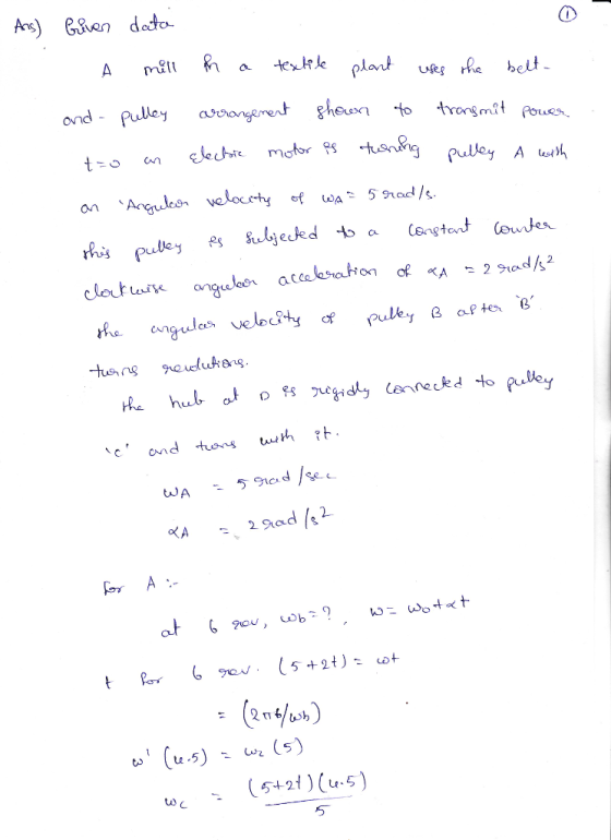
 6. A mill in a textile plant uses the belt-and-pulley arrangement shown below to transmit power. Pulley A rotates with an angular acceleration of aA = (10t + 5) rad/s, where t is in seconds. The hub at D is rigidly connected to pulley C and turn with it. Pulley A has an angular velocity of 15 rad/s when t=0s. i) Determine the angular velocity and angular displacement of Pulley A when t=2s ii) Determine the angular velocity and angular...
Q1 A belt drive and pulley arrangement is designed to transmit 75 kW of power at 1200 rpm, genera...
Q1 A belt drive and pulley arrangement is designed to transmit 75 kW of power at 1200 rpm, generated by a six-pole squirrel-cage induction motor. The belt connects two shafts 3 m apart, with axes in the same horizontal plane. The driven shaft runs at half the angular speed of the driver and it runs a light shock machinery. As a design engineer you need to do the following; i. Design shafts suitable for this application (20 marks) ii. Select...
An electric motor turns a llywheel through a drive belt that joins a pulley on the...
 An electric motor turns a llywheel through a drive belt that joins a pulley on the motor and a pulley that is rigidly attached to the flywheel as shown in the figure below. The flywheel is a solid disk with a mass of 53.0 kg and a radius R -0.625 m. It turns on a frictionless axle. Its pulley has much smaller mass and a radius of 0.230 m. The tersion in the upper (taut) segment of the belt is...
At the instant wa= 7 rad/s, pulley A is given an angular acceleration a= (0.70) rad/s,...
 At the instant wa= 7 rad/s, pulley A is given an angular acceleration a= (0.70) rad/s, where is in radians. Pulley Chas an inner hub which is fixed to its outer one and turns with it. (Figure 1) Part A Determine the magnitude of acceleration of point B on Pulley C when A rotates 3 revolutions. Express your answer to three significant figures and include the appropriate units. ? C: HÅR Value O Units ab = Submit Request Answer Provide...
<Homework for MO3.2 14 of 17 Rotation about a Fixed Axis A Review Part B Learning...
 <Homework for MO3.2 14 of 17 Rotation about a Fixed Axis A Review Part B Learning Goal: To use the kinematic relationships for rotation about a fixed ads to determine the number of revolutions for an accelerating pulley The two pulleys shown in (Figure 1) are connected by a belt, which is assumed to not slip with radila = 30 mm and re - 60 mm. Pulley A has been spinning at a constant WA = 4 rad/s Att0 pulley...
Problem 1: Power transmission in a composite shaft A aluminum-steel composite shaft is used to transmit...
 Problem 1: Power transmission in a composite shaft A aluminum-steel composite shaft is used to transmit power from one pulley to another, as shown in the following figure 2b tal tbl 2a t32 tb2 μι 2a Because the shaft is designed poorly, the center bearing exerts a frictional moment of Mfrictionw where K is the viscous coefficient and w is the angular velocity of the shaft Let L = 1 m, a-5cm, b = 1 cm, c-1 cm, with 6061...
please help with solving the variables in the drawing of the photo (rc, wc, wb, rb,...
 please help with solving the variables in the drawing of the photo
(rc, wc, wb, rb, ra) and please include an explantion of how it
would work
Dynamics Project: Part 1 Project Description: The saw blade in a lumber mill is required to remain in the horizontal position and undergo a complete Dack-and-forth motion in 2 seconds. An electric motor having a shaft rotation of 50 rad/s constant, is available to power the saw and can be located anywhere. Design...
please help with solving the variables in the drawing of the photo
(rc, wc, wb, rb, ra) and please include an explantion of how it
would work
Dynamics Project: Part 1 Project Description: The saw blade in a lumber mill is required to remain in the horizontal position and undergo a complete Dack-and-forth motion in 2 seconds. An electric motor having a shaft rotation of 50 rad/s constant, is available to power the saw and can be located anywhere. Design...
5:16 lLTE ) Done 1 of 5 Assessment #1 (Kinematics of a Particle) Rectilinear Motion (Straight...
 5:16 lLTE ) Done 1 of 5 Assessment #1 (Kinematics of a Particle) Rectilinear Motion (Straight linc Motion 3. The position of a point during the interval of time from r otor 6 is given by ** * m. (a) What is the maximum velocity during this interval of time, and at what time does it occur? (b) What is the acceleration when the velocity is a maximum? (20 m/s, 0 m/s 3. A test projectile is fired horizontally into...
 6. A mill in a textile plant uses the belt-and-pulley arrangement shown below to transmit power. Pulley A rotates with an angular acceleration of aA = (10t + 5) rad/s, where t is in seconds. The hub at D is rigidly connected to pulley C and turn with it. Pulley A has an angular velocity of 15 rad/s when t=0s. i) Determine the angular velocity and angular displacement of Pulley A when t=2s ii) Determine the angular velocity and angular...
 An electric motor turns a llywheel through a drive belt that joins a pulley on the motor and a pulley that is rigidly attached to the flywheel as shown in the figure below. The flywheel is a solid disk with a mass of 53.0 kg and a radius R -0.625 m. It turns on a frictionless axle. Its pulley has much smaller mass and a radius of 0.230 m. The tersion in the upper (taut) segment of the belt is...
 At the instant wa= 7 rad/s, pulley A is given an angular acceleration a= (0.70) rad/s, where is in radians. Pulley Chas an inner hub which is fixed to its outer one and turns with it. (Figure 1) Part A Determine the magnitude of acceleration of point B on Pulley C when A rotates 3 revolutions. Express your answer to three significant figures and include the appropriate units. ? C: HÅR Value O Units ab = Submit Request Answer Provide...
 <Homework for MO3.2 14 of 17 Rotation about a Fixed Axis A Review Part B Learning Goal: To use the kinematic relationships for rotation about a fixed ads to determine the number of revolutions for an accelerating pulley The two pulleys shown in (Figure 1) are connected by a belt, which is assumed to not slip with radila = 30 mm and re - 60 mm. Pulley A has been spinning at a constant WA = 4 rad/s Att0 pulley...
 Problem 1: Power transmission in a composite shaft A aluminum-steel composite shaft is used to transmit power from one pulley to another, as shown in the following figure 2b tal tbl 2a t32 tb2 μι 2a Because the shaft is designed poorly, the center bearing exerts a frictional moment of Mfrictionw where K is the viscous coefficient and w is the angular velocity of the shaft Let L = 1 m, a-5cm, b = 1 cm, c-1 cm, with 6061...
 please help with solving the variables in the drawing of the photo
(rc, wc, wb, rb, ra) and please include an explantion of how it
would work
Dynamics Project: Part 1 Project Description: The saw blade in a lumber mill is required to remain in the horizontal position and undergo a complete Dack-and-forth motion in 2 seconds. An electric motor having a shaft rotation of 50 rad/s constant, is available to power the saw and can be located anywhere. Design...
please help with solving the variables in the drawing of the photo
(rc, wc, wb, rb, ra) and please include an explantion of how it
would work
Dynamics Project: Part 1 Project Description: The saw blade in a lumber mill is required to remain in the horizontal position and undergo a complete Dack-and-forth motion in 2 seconds. An electric motor having a shaft rotation of 50 rad/s constant, is available to power the saw and can be located anywhere. Design...
 5:16 lLTE ) Done 1 of 5 Assessment #1 (Kinematics of a Particle) Rectilinear Motion (Straight linc Motion 3. The position of a point during the interval of time from r otor 6 is given by ** * m. (a) What is the maximum velocity during this interval of time, and at what time does it occur? (b) What is the acceleration when the velocity is a maximum? (20 m/s, 0 m/s 3. A test projectile is fired horizontally into...
Most questions answered within 3 hours.
-
A comet orbits the Sun every 8.67 years and reaches its
closest distance to the Sun...
asked 5 minutes ago -
Draw the structure of the compound: 1,1-diethyl-4-
(3,3-dimethylbutyl) cyclohexane.
asked 2 minutes ago -
An inductor with L = 9.70 mH is connected across an ac source
that has voltage...
asked 8 minutes ago -
Karsh has been breeding two different types of angel fish: a
common breed and a rare...
asked 27 minutes ago -
Job postings often state that the successful applicant
must have superior critical thinking and problem-solving skills....
asked 21 minutes ago -
What is the total cost of full ESP Pump equipments (down hole
equipment and upper surface...
asked 19 minutes ago -
cpp
Description
The purpose of this challenge is to use the for loops. This
challenge uses...
asked 28 minutes ago -
1. Drag the statements to the correct type of medium to compare
and contrast different examples...
asked 27 minutes ago -
"Please Solve Problem 2 Please"
Program 1(Total Point 15): You will use scanner class and ask...
asked 30 minutes ago -
If a counting standard has a mean activity of 400 cpm, what is
the probability of...
asked 30 minutes ago -
From the definition of torque in terms of angular momentum, ?
⃗=??/??, show that ??/??=−??/? where...
asked 30 minutes ago -
Please show calculations/work
Marcello is filing as single and has 2018 taxable income of
$730,000 which...
asked 1 hour ago