
Homework Answers


Add Answer to:
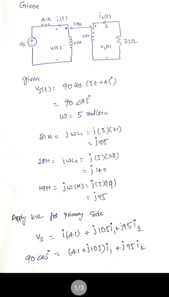
(0) 41 10 19H Problem 11.9-19 (Companion Problem 2) (1) 321H28 HS v2(0) 3732 Primary Secondary...
i PRINTER VERSION BACK NEXT Problem 11.9-19 (Companion Problem 2) 43 (0) 21H 20 w ASSIGNMENT...
 i PRINTER VERSION BACK NEXT Problem 11.9-19 (Companion Problem 2) 43 (0) 21H 20 w ASSIGNMENT RESOURCES HW.6 Problem 11.9-3 Problem 11.9-18 (Companion Problem 1). Problem 11.9-18 (Companion Problem 2) Problem 11.9-19 (Companion Problem 1). Problem 11.9-19 (Companion Problem 2) vio) 324H 30 HB v2(1) 3642 Primary Secondary The input to this circuit is the voltage source voltage Vs(t) = 92cos (8t+45) v Review Score Review Results by Study Objective Determine the complex power supplied by the voltage source: s....
Problem 13.2-4 erial.11 oblem 13.2-3 roblem 13.2-4 oblem 13.2-4 Companion Problem) xample 16.7-1 9222 32 3...
 Problem 13.2-4 erial.11 oblem 13.2-3 roblem 13.2-4 oblem 13.2-4 Companion Problem) xample 16.7-1 9222 32 3 v.(0) 0.4H 3 ew Score ew Results by Study ective Site volt) The input to this circuit is the voltage-source voltage, vs(t). The output is the voltage, vo(t), across the series inductor and 32-S2 resistor. The network function of this circuit is H(W) * Determine the values of the constants k, z and p. k= V/V, z = 0 rad/s and p = c...
Problem 1: The secondary winding of a transformer has a terminal voltage of v, (t) 282.8...
 Problem 1: The secondary winding of a transformer has a terminal voltage of v, (t) 282.8 sin 377t V. The turns ratio of the transformer is 100:200 (a0.50) The impedances of this transformer referred to the primary side are The equivalent circuit is shown below lf (a) If the secondary current of the transformer is i,()-7.07sin(3771-36.87) A, what is the primary current of this transformer? (20 points) HINTS: I. Peak values of the secondary voltage and current are specified in...
Problem 10.6-19 4 H 2 4 m 3 15 2 vy(t) 27 1 = v(t) 3...
 Problem 10.6-19 4 H 2 4 m 3 15 2 vy(t) 27 1 = v(t) 3 vit) $ 20 mF + v.(t) The input to this circuit the voltage source voltage is vs(t) = 8 cos(2 t) V. First, represent the circuit in the frequency domain using phasors and impedances. next, Apply KCL at nodes 2 and 4 and arrange the results in matrix form to to obtain the node equations: Tatjo 0 T 13-1-ja VO [, 1-ja][M]-[:) Determine the...
V2 = 8 (V) Ry = 8 (0) V2 = 26 (V) Problem 1 Using Kirchhoff's...
 V2 = 8 (V) Ry = 8 (0) V2 = 26 (V) Problem 1 Using Kirchhoff's rules in the circuit of image, A- Calculate the current in the circuit. B- Show the direction current in the circuit. C- Calculate the voltage across resistor R1 D- Calculate the power delivered to R2 E- After 15 minutes of working of circuit, how much energy is delivered to resistor Rı? T-28 V2 = 28 (V) V3 = 20 (7) R2 = 7(0)
Text problem 2.4: A single-phase source supplies a load of R 25 2 and a reactance...
 Text problem 2.4: A single-phase source supplies a load of R 25 2 and a reactance of Xc - are commected in paralel. The " 15 2, both of which are connected in parallel. The voltage across the combination is v(t) - v2(120) cos(wt -45°) v. a) Find V, the total current I, instantaneous current i(t), and the complex power. b) Repeat a) if instead of the capacitive reactance we had inductive reactance of XL = 20 Ω (Partial answer:...
Example 10.5-3 (See Example 10.5-3 in the textbook for the solution to a similar problem.) 2...
 Example 10.5-3 (See Example 10.5-3 in the textbook for the solution to a similar problem.) 2 mF 13o This circuit is at steady state. The input to this circuit is the voltage source voltage, vs(t), given by Vs(t) = 45cos(20t + (-50° ) | V The output voltage, Vo(t), can be expressed as Vo (t) = A cos(20t+ θ) v where A and θ are constants such that A > 0 and-180° < θ < 180°. Determine the values of...
Example 10.5-1 (See Example 10.5-1 in the textbook for the solution to a similar problem.) 68Ω...
 Example 10.5-1 (See Example 10.5-1 in the textbook for the solution to a similar problem.) 68Ω i(t) yso) 6.0H This circuit is at steady state. The input to this circuit is the voltage source voltage, vs(t), given by Vs(t) = 22cos(12t + (35° ) v The steady-state mesh current, (t), can be expressed as i(t)-A cos(12t + θ) mA 1809. Determine the values of the constants A and θ: where A and θ are constants such that A > 0...
problem 7 Problem-4 [10 Points] Find the Laplace transforms of the functions in Figure. 2 Figure....
 problem 7
Problem-4 [10 Points] Find the Laplace transforms of the functions in Figure. 2 Figure. 2: Triangular Function Problem-5 [10 Pointsl A system has the transfer function h(s) = (s1)(s +2) a) Find the impulse response of the system b) Determine the output y(t), given that the input is x(t) u(t) Problem-6 [10 Pointsl Use the Laplace transform to solve the differential equation +22+10v(t) 3 cos(2t) dt2 dt subject to v(0)-1, dv(O) Problem-7 [10 Points] Solve the integrodifferential equation...
problem 7
Problem-4 [10 Points] Find the Laplace transforms of the functions in Figure. 2 Figure. 2: Triangular Function Problem-5 [10 Pointsl A system has the transfer function h(s) = (s1)(s +2) a) Find the impulse response of the system b) Determine the output y(t), given that the input is x(t) u(t) Problem-6 [10 Pointsl Use the Laplace transform to solve the differential equation +22+10v(t) 3 cos(2t) dt2 dt subject to v(0)-1, dv(O) Problem-7 [10 Points] Solve the integrodifferential equation...
please help with 1&2 Problem i. Common-Gate Amplifier: Assume kp = 2 mA/V, VTp = -1...
 please help with 1&2
Problem i. Common-Gate Amplifier: Assume kp = 2 mA/V, VTp = -1 V.=y=0. Determine the following: (5 pt) 1) Vos and VDS (5 pt) 2) The small-signal parameters, go andro (7.5 pt) 3) Draw small-signal equivalent circuit (7.5 pt) 4) Input Resistance, Rin (7.5 pt) 5) Output Resistance, Rout (15 pt) 6) Small-signal Voltage Gain; A, = Yout +15 V -15 V ima 0 1 ko 50 kn Rout (50 pt) Problem 2. Common-Source Amplifier: Assume...
please help with 1&2
Problem i. Common-Gate Amplifier: Assume kp = 2 mA/V, VTp = -1 V.=y=0. Determine the following: (5 pt) 1) Vos and VDS (5 pt) 2) The small-signal parameters, go andro (7.5 pt) 3) Draw small-signal equivalent circuit (7.5 pt) 4) Input Resistance, Rin (7.5 pt) 5) Output Resistance, Rout (15 pt) 6) Small-signal Voltage Gain; A, = Yout +15 V -15 V ima 0 1 ko 50 kn Rout (50 pt) Problem 2. Common-Source Amplifier: Assume...
 i PRINTER VERSION BACK NEXT Problem 11.9-19 (Companion Problem 2) 43 (0) 21H 20 w ASSIGNMENT RESOURCES HW.6 Problem 11.9-3 Problem 11.9-18 (Companion Problem 1). Problem 11.9-18 (Companion Problem 2) Problem 11.9-19 (Companion Problem 1). Problem 11.9-19 (Companion Problem 2) vio) 324H 30 HB v2(1) 3642 Primary Secondary The input to this circuit is the voltage source voltage Vs(t) = 92cos (8t+45) v Review Score Review Results by Study Objective Determine the complex power supplied by the voltage source: s....
 Problem 13.2-4 erial.11 oblem 13.2-3 roblem 13.2-4 oblem 13.2-4 Companion Problem) xample 16.7-1 9222 32 3 v.(0) 0.4H 3 ew Score ew Results by Study ective Site volt) The input to this circuit is the voltage-source voltage, vs(t). The output is the voltage, vo(t), across the series inductor and 32-S2 resistor. The network function of this circuit is H(W) * Determine the values of the constants k, z and p. k= V/V, z = 0 rad/s and p = c...
 Problem 1: The secondary winding of a transformer has a terminal voltage of v, (t) 282.8 sin 377t V. The turns ratio of the transformer is 100:200 (a0.50) The impedances of this transformer referred to the primary side are The equivalent circuit is shown below lf (a) If the secondary current of the transformer is i,()-7.07sin(3771-36.87) A, what is the primary current of this transformer? (20 points) HINTS: I. Peak values of the secondary voltage and current are specified in...
 Problem 10.6-19 4 H 2 4 m 3 15 2 vy(t) 27 1 = v(t) 3 vit) $ 20 mF + v.(t) The input to this circuit the voltage source voltage is vs(t) = 8 cos(2 t) V. First, represent the circuit in the frequency domain using phasors and impedances. next, Apply KCL at nodes 2 and 4 and arrange the results in matrix form to to obtain the node equations: Tatjo 0 T 13-1-ja VO [, 1-ja][M]-[:) Determine the...
 V2 = 8 (V) Ry = 8 (0) V2 = 26 (V) Problem 1 Using Kirchhoff's rules in the circuit of image, A- Calculate the current in the circuit. B- Show the direction current in the circuit. C- Calculate the voltage across resistor R1 D- Calculate the power delivered to R2 E- After 15 minutes of working of circuit, how much energy is delivered to resistor Rı? T-28 V2 = 28 (V) V3 = 20 (7) R2 = 7(0)
 Text problem 2.4: A single-phase source supplies a load of R 25 2 and a reactance of Xc - are commected in paralel. The " 15 2, both of which are connected in parallel. The voltage across the combination is v(t) - v2(120) cos(wt -45°) v. a) Find V, the total current I, instantaneous current i(t), and the complex power. b) Repeat a) if instead of the capacitive reactance we had inductive reactance of XL = 20 Ω (Partial answer:...
 Example 10.5-3 (See Example 10.5-3 in the textbook for the solution to a similar problem.) 2 mF 13o This circuit is at steady state. The input to this circuit is the voltage source voltage, vs(t), given by Vs(t) = 45cos(20t + (-50° ) | V The output voltage, Vo(t), can be expressed as Vo (t) = A cos(20t+ θ) v where A and θ are constants such that A > 0 and-180° < θ < 180°. Determine the values of...
 Example 10.5-1 (See Example 10.5-1 in the textbook for the solution to a similar problem.) 68Ω i(t) yso) 6.0H This circuit is at steady state. The input to this circuit is the voltage source voltage, vs(t), given by Vs(t) = 22cos(12t + (35° ) v The steady-state mesh current, (t), can be expressed as i(t)-A cos(12t + θ) mA 1809. Determine the values of the constants A and θ: where A and θ are constants such that A > 0...
 problem 7
Problem-4 [10 Points] Find the Laplace transforms of the functions in Figure. 2 Figure. 2: Triangular Function Problem-5 [10 Pointsl A system has the transfer function h(s) = (s1)(s +2) a) Find the impulse response of the system b) Determine the output y(t), given that the input is x(t) u(t) Problem-6 [10 Pointsl Use the Laplace transform to solve the differential equation +22+10v(t) 3 cos(2t) dt2 dt subject to v(0)-1, dv(O) Problem-7 [10 Points] Solve the integrodifferential equation...
problem 7
Problem-4 [10 Points] Find the Laplace transforms of the functions in Figure. 2 Figure. 2: Triangular Function Problem-5 [10 Pointsl A system has the transfer function h(s) = (s1)(s +2) a) Find the impulse response of the system b) Determine the output y(t), given that the input is x(t) u(t) Problem-6 [10 Pointsl Use the Laplace transform to solve the differential equation +22+10v(t) 3 cos(2t) dt2 dt subject to v(0)-1, dv(O) Problem-7 [10 Points] Solve the integrodifferential equation...
 please help with 1&2
Problem i. Common-Gate Amplifier: Assume kp = 2 mA/V, VTp = -1 V.=y=0. Determine the following: (5 pt) 1) Vos and VDS (5 pt) 2) The small-signal parameters, go andro (7.5 pt) 3) Draw small-signal equivalent circuit (7.5 pt) 4) Input Resistance, Rin (7.5 pt) 5) Output Resistance, Rout (15 pt) 6) Small-signal Voltage Gain; A, = Yout +15 V -15 V ima 0 1 ko 50 kn Rout (50 pt) Problem 2. Common-Source Amplifier: Assume...
please help with 1&2
Problem i. Common-Gate Amplifier: Assume kp = 2 mA/V, VTp = -1 V.=y=0. Determine the following: (5 pt) 1) Vos and VDS (5 pt) 2) The small-signal parameters, go andro (7.5 pt) 3) Draw small-signal equivalent circuit (7.5 pt) 4) Input Resistance, Rin (7.5 pt) 5) Output Resistance, Rout (15 pt) 6) Small-signal Voltage Gain; A, = Yout +15 V -15 V ima 0 1 ko 50 kn Rout (50 pt) Problem 2. Common-Source Amplifier: Assume...
Most questions answered within 3 hours.
-
Vaughn Manufacturing acquires a coal mine at a cost of $1870000.
Intangible development costs total $354000....
asked 9 seconds ago -
Question 5
What effect would a decrease in
temperature have on pressure, assuming that volume
(T)...
asked 12 minutes ago -
QUESTION 6
Determine the linear momentum of a 2,800 kg houseboat going 3
m/s.
9,100 kg.m/s...
asked 10 minutes ago -
Draw the Lewis dot structures for the following molecules. None
of the atoms have a formal...
asked 17 minutes ago -
Jor-el throws a ball upward from the top of a 728 foot building
on the planet...
asked 14 minutes ago -
What does it mean when an element is radioactive?
a.
It means the element is changing...
asked 17 minutes ago -
A company deposits $6,000 in a bank at the end of every year for
10 years....
asked 17 minutes ago -
What are some strategies for eliminating service barriers?
By using your knowledge of
behavioral styles, please...
asked 25 minutes ago -
What are the decimal numbers for 159, 150, 200, 113, 225, 87,
106, 81 when converted...
asked 33 minutes ago -
Calculate and plot the number and weight distributions of x-mers
found in a step-growth polymerization for...
asked 52 minutes ago -
The Baily Corporation has developed a specialized software
program that improves inventory control capability. The following...
asked 56 minutes ago -
Problem 5-4A (Part Level Submission) Wolford Department Store is
located in midtown Metropolis. During the past...
asked 56 minutes ago