
Homework Answers
Add Answer to:
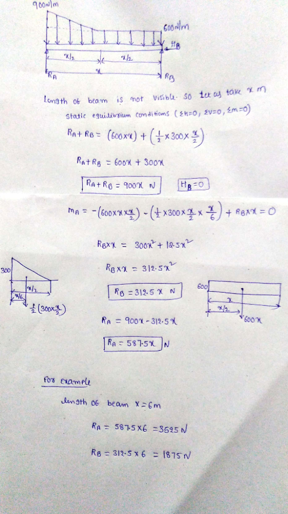
3. Determine the reactions at the supports shown in the following figure. The beam has a...
Determine the reactions at the supports A and B of the beam shown below.
 Determine the reactions at the supports A and B of the beam shown below. A is a pin support and B is a roller
Q3. a. Determine the reactions at supports A and B for the beam as shown in...
 Q3. a. Determine the reactions at supports A and B for the beam as shown in figure below. (Assume support A is a roller and support B hinged) 15.01 22 N/m 15 N 50 Nm B А 6.5 m 3.5 m b. Draw the free body diagram of each of the blocks given in the figure below. [2.5)
A beam supports a variably distributed load as shown in Figure 3. Given a pin support...
 A beam supports a variably distributed load as shown in Figure 3. Given a pin support at A, and a roller support at B, calculate the support reactions. Lw 6 kN/m lw 2 kN/m 2 m Figure 3 Beam supporting a variably distributed load
Determine the reactions at the supports of the beam which is loaded as shown. Assume w1...
 Determine the reactions at the supports of the beam which is
loaded as shown.
Assume w1 = 600 N/m, w2 =
220 N/m, a = 7.1 m, b = 1.8 m.
Determine the reactions at the supports of the beam which is loaded as shown. Assume w1 = 600 N/m, W2 = 220 N/m, a = 7.1m, b = 1.8 m. w w OB b b d Answers Ax - N Ay = N By = N
Determine the reactions at the supports of the beam which is
loaded as shown.
Assume w1 = 600 N/m, w2 =
220 N/m, a = 7.1 m, b = 1.8 m.
Determine the reactions at the supports of the beam which is loaded as shown. Assume w1 = 600 N/m, W2 = 220 N/m, a = 7.1m, b = 1.8 m. w w OB b b d Answers Ax - N Ay = N By = N
1) Determine the reactions at the supports for the structures shown. The support at A is...
 1) Determine the reactions at the supports for the structures shown. The support at A is a Roller and the support at B is a Pin. 2.0 k/ft M 10 k- 3.0 k/ft 12 ft 25 k- 25k-Pokift 15 ft B! 1 F20ft- 2) 2 3 k/ft A beam is supported at points A, C, and E, and is loaded as shown. The support at A is fixed. The supports at C and E are rollers. Hinge-B ce Dl Hinge...
1. The frame supports the load as shown. The pin at A has a diameter of...
 1. The frame supports the load as shown. The pin at A has a diameter of 0.3 in. If pin at A is subjected to double shear, determine the average shear stress in the pin. Note that support at B is a roller. (25 points) -2 ft 36 in 3 ft 900 O -900 t(품)g0otAc 24i 1. The frame supports the load as shown. The pin at A has a diameter of 0.3 in. If pin at A is subjected...
Calculate the reactions at the supports A, B, and C for the beam in figure 4...
 Calculate the reactions at the supports A, B, and C for the beam in figure 4 and then draw the shear force and bending moment diagrams. At A and B there are simple supports while at C there is a pin joint. If the cross section of the beam is rectangular, with dimensions b-10 mm and h-24 mm what is maximum bending stress in the beam? 12 kN 9 kN/m 22 224m 2
- 3- Determine the reactions on the beam shown. Assume A is a pin and the...
 - 3- Determine the reactions on the beam shown. Assume A is a pin and the support at B is a roller (smooth surface). 10KN m BA 3m 4m am A न
Using force method , determine the reactions of the supports for the beam shown in Figure...
 Using force method , determine the reactions of the
supports for the beam shown in Figure ( 5 ) . Then draw shear and
bending moment diagrams for the beam El is constant Use conjugate
beam method to determine deflections ,
6 m 50 KN 200 kN. 9 m - 3 m Fig. (5) BEST WISHES
Using force method , determine the reactions of the
supports for the beam shown in Figure ( 5 ) . Then draw shear and
bending moment diagrams for the beam El is constant Use conjugate
beam method to determine deflections ,
6 m 50 KN 200 kN. 9 m - 3 m Fig. (5) BEST WISHES
(b) Equilibrium of a compound beam is maintained by the fixed, pin and roller supports at A, B and C respectively. F...
 (b) Equilibrium of a compound beam is maintained by the fixed, pin and roller supports at A, B and C respectively. For the following loading, determine the reactions at the supports A, B and C 20 kN 6 kN/m 2 m 2 m rn
(b) Equilibrium of a compound beam is maintained by the fixed, pin and roller supports at A, B and C respectively. For the following loading, determine the reactions at the supports A, B and C 20...
(b) Equilibrium of a compound beam is maintained by the fixed, pin and roller supports at A, B and C respectively. For the following loading, determine the reactions at the supports A, B and C 20 kN 6 kN/m 2 m 2 m rn
(b) Equilibrium of a compound beam is maintained by the fixed, pin and roller supports at A, B and C respectively. For the following loading, determine the reactions at the supports A, B and C 20...
 Q3. a. Determine the reactions at supports A and B for the beam as shown in figure below. (Assume support A is a roller and support B hinged) 15.01 22 N/m 15 N 50 Nm B А 6.5 m 3.5 m b. Draw the free body diagram of each of the blocks given in the figure below. [2.5)
 A beam supports a variably distributed load as shown in Figure 3. Given a pin support at A, and a roller support at B, calculate the support reactions. Lw 6 kN/m lw 2 kN/m 2 m Figure 3 Beam supporting a variably distributed load
 Determine the reactions at the supports of the beam which is
loaded as shown.
Assume w1 = 600 N/m, w2 =
220 N/m, a = 7.1 m, b = 1.8 m.
Determine the reactions at the supports of the beam which is loaded as shown. Assume w1 = 600 N/m, W2 = 220 N/m, a = 7.1m, b = 1.8 m. w w OB b b d Answers Ax - N Ay = N By = N
Determine the reactions at the supports of the beam which is
loaded as shown.
Assume w1 = 600 N/m, w2 =
220 N/m, a = 7.1 m, b = 1.8 m.
Determine the reactions at the supports of the beam which is loaded as shown. Assume w1 = 600 N/m, W2 = 220 N/m, a = 7.1m, b = 1.8 m. w w OB b b d Answers Ax - N Ay = N By = N
 1) Determine the reactions at the supports for the structures shown. The support at A is a Roller and the support at B is a Pin. 2.0 k/ft M 10 k- 3.0 k/ft 12 ft 25 k- 25k-Pokift 15 ft B! 1 F20ft- 2) 2 3 k/ft A beam is supported at points A, C, and E, and is loaded as shown. The support at A is fixed. The supports at C and E are rollers. Hinge-B ce Dl Hinge...
 1. The frame supports the load as shown. The pin at A has a diameter of 0.3 in. If pin at A is subjected to double shear, determine the average shear stress in the pin. Note that support at B is a roller. (25 points) -2 ft 36 in 3 ft 900 O -900 t(품)g0otAc 24i 1. The frame supports the load as shown. The pin at A has a diameter of 0.3 in. If pin at A is subjected...
 Calculate the reactions at the supports A, B, and C for the beam in figure 4 and then draw the shear force and bending moment diagrams. At A and B there are simple supports while at C there is a pin joint. If the cross section of the beam is rectangular, with dimensions b-10 mm and h-24 mm what is maximum bending stress in the beam? 12 kN 9 kN/m 22 224m 2
 - 3- Determine the reactions on the beam shown. Assume A is a pin and the support at B is a roller (smooth surface). 10KN m BA 3m 4m am A न
 Using force method , determine the reactions of the
supports for the beam shown in Figure ( 5 ) . Then draw shear and
bending moment diagrams for the beam El is constant Use conjugate
beam method to determine deflections ,
6 m 50 KN 200 kN. 9 m - 3 m Fig. (5) BEST WISHES
Using force method , determine the reactions of the
supports for the beam shown in Figure ( 5 ) . Then draw shear and
bending moment diagrams for the beam El is constant Use conjugate
beam method to determine deflections ,
6 m 50 KN 200 kN. 9 m - 3 m Fig. (5) BEST WISHES
 (b) Equilibrium of a compound beam is maintained by the fixed, pin and roller supports at A, B and C respectively. For the following loading, determine the reactions at the supports A, B and C 20 kN 6 kN/m 2 m 2 m rn
(b) Equilibrium of a compound beam is maintained by the fixed, pin and roller supports at A, B and C respectively. For the following loading, determine the reactions at the supports A, B and C 20...
(b) Equilibrium of a compound beam is maintained by the fixed, pin and roller supports at A, B and C respectively. For the following loading, determine the reactions at the supports A, B and C 20 kN 6 kN/m 2 m 2 m rn
(b) Equilibrium of a compound beam is maintained by the fixed, pin and roller supports at A, B and C respectively. For the following loading, determine the reactions at the supports A, B and C 20...
Most questions answered within 3 hours.
-
A university administrator working in student housing wants to
determine if the percentage of students residing...
asked 6 minutes ago -
3). Describe human population growth that has occurred in the
past 400 years. Use terms learned...
asked 3 minutes ago -
A
projectile is blue at a target. The distance from the point of
impact to the...
asked 28 minutes ago -
Given a 32 bit processor, with 2 MB of physical RAM split into 512
frames. What...
asked 18 minutes ago -
What were the main rulings in the Supreme Court cases which are
Morgan v. Virginia (1946)...
asked 17 minutes ago -
write a five paragraph essay on how setting,
specifically culture, influences the actions of
the characters...
asked 9 minutes ago -
JAVA
Provide a simple code sample of Merge sort
asked 20 minutes ago -
Discounting cash flows involves:
A. taking the cash discount offered on a trade merchandise
B. estimating...
asked 27 minutes ago -
A solid wood door 1.00 m wide and 2.00 m high is hinged along
one side...
asked 27 minutes ago -
Raleigh Company manufactures two joint products. At the
split-off point, they have sales values of:
Product...
asked 27 minutes ago -
1. Your grandmother has invested $4000 in a mutual fund each
year on your birthday (she...
asked 29 minutes ago -
HELP WITH SAS
Run the following DATA step to create a SAS data set called
ABC_CORP....
asked 42 minutes ago