
Homework Answers
Add Answer to:
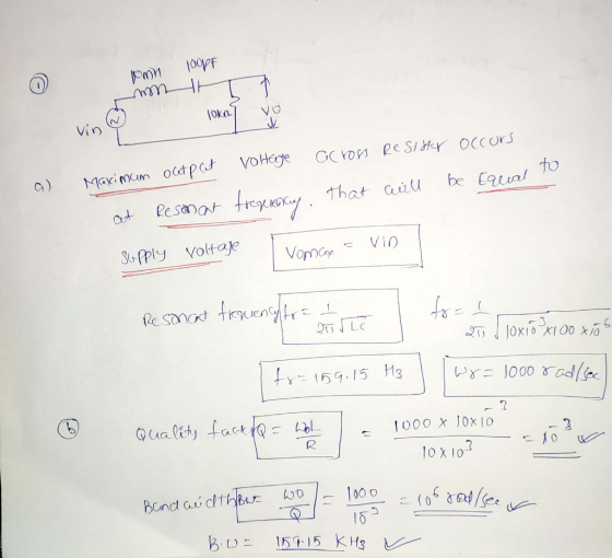
1. Consider a series RLC circuit with input voltage source Vin and the output voltage V,...
Consider a RLC series circuit connected to a 220 V rms voltage source with a frequency...
Consider a RLC series circuit connected to a 220 V rms voltage source with a frequency of 120 Hz. WhatConsider a RLC series circuit connected to a 220 V rms voltage source with a frequency of 120 Hz. What is the peak current through the circuit if R = 250Ω, C = 90 μF, and L = 4.5 mH?is the peak current through the circuit if R = 250Ω, C = 90 μF, and L = 4.5 mH? A. 1.24...
4. Consider a series RLC circuit driven by a voltage source with capacitor voltage as output. Ass...
 4. Consider a series RLC circuit driven by a voltage source with capacitor voltage as output. Assume the following parameter values: R 20n, L ;: 1 mH, C : 5μF a. b. c. d. Write down the transfer function of the system Choose a sample time for the system Find the pulse transfer function (use MATLAB 'c2d' command) Find the range of K for stability for the closed-loop sampled-data system
4. Consider a series RLC circuit driven by a voltage...
4. Consider a series RLC circuit driven by a voltage source with capacitor voltage as output. Assume the following parameter values: R 20n, L ;: 1 mH, C : 5μF a. b. c. d. Write down the transfer function of the system Choose a sample time for the system Find the pulse transfer function (use MATLAB 'c2d' command) Find the range of K for stability for the closed-loop sampled-data system
4. Consider a series RLC circuit driven by a voltage...
4. Show that a series LR circuit is a lowpass filter if the output is taken...
 4. Show that a series LR circuit is a lowpass filter if the output is taken across the resistor. Calculate the corner frequency fc if L-20 mH and R 10 5. The circuit parameters for a series RLC bandstop filter are R-200 Ω, L-1 mH, C 40 pF. Calculate: (a) the center frequency (b) the half-power frequencies (c) the quality factor.
For an RLC series circuit, the voltage amplitude and frequency of the source are 100 V...
 For an RLC series circuit, the voltage amplitude and frequency of the source are 100 V and 500 Hz, respectively; R = 520 , and L 0.34 H. Find the average power (in W) dissipated in the resistor for the following values for the capacitance. (a) C 3.6 HF 4.55 XW (b) C 0.36 HF
Consider a series RLC circuit where the output voltage y(t) is taken across the resistor and...
Consider a series RLC circuit where the output voltage y(t) is taken across the resistor and the input is the voltage x(t). WHAT TYPE OF FILTER IS THIS?
Consider a series RLC circuit where the output voltage y(t) is taken across the resistor and...
Consider a series RLC circuit where the output voltage y(t) is taken across the resistor and the input is the voltage x(t). (a) Find the transfer function of this filter. (b) What is the type of this filter?
Consider the series RLC circuit in Figure 1. Suppose the source voltage is initially OV, and...
 Consider the series RLC circuit in Figure 1. Suppose the source voltage is initially OV, and no energy is stored in both the capacitor and inductor. At t = 0, the source voltage is switched to 1V. Calculate the resistor, inductor and capacitor voltages, and the loop current V (t),,(t),Vc(t),i(t). Show all the steps. C1 L1 1.2u 8.2m 10 3 R1 Figure 1: A series RLC circuit
For an RLC series circuit, R - 110 0, L 210 mH, and c- 0.29 uF....
 For an RLC series circuit, R - 110 0, L 210 mH, and c- 0.29 uF. = 0.29 (a) If an AC source of variable frequency is connected to the circuit, at what frequency (in Hz) is maximum power dissipated in the resistor? Hz (b) What is the quality factor of the circuit? Q=
An alternating source drives a series RLC circuit with an emf amplitude of 6.0 V. The...
 An alternating source drives a series RLC circuit with an emf amplitude of 6.0 V. The following three elements are connected in series: a resistor of 1812, a 24 mH inductor, and a 0.50 pF capacitor. What is the amplitude of the potential difference across the inductor, in V, at resonance?
Consider the series RLC circuit in Figure 1. Suppose the source voltage is initially OV, and...
 Consider the series RLC circuit in Figure 1. Suppose the source voltage is initially OV, and no energy is stored in both the capacitor and inductor. At t = 0, the source voltage is switched to 1V. Calculate the resistor, inductor and capacitor voltages, and the loop current VROV.O.Vc),it). Show all the steps. SOL L1 n 8.2m 10 3 R1 Figure 1: A series RLC circuit
 4. Consider a series RLC circuit driven by a voltage source with capacitor voltage as output. Assume the following parameter values: R 20n, L ;: 1 mH, C : 5μF a. b. c. d. Write down the transfer function of the system Choose a sample time for the system Find the pulse transfer function (use MATLAB 'c2d' command) Find the range of K for stability for the closed-loop sampled-data system
4. Consider a series RLC circuit driven by a voltage...
4. Consider a series RLC circuit driven by a voltage source with capacitor voltage as output. Assume the following parameter values: R 20n, L ;: 1 mH, C : 5μF a. b. c. d. Write down the transfer function of the system Choose a sample time for the system Find the pulse transfer function (use MATLAB 'c2d' command) Find the range of K for stability for the closed-loop sampled-data system
4. Consider a series RLC circuit driven by a voltage...
 4. Show that a series LR circuit is a lowpass filter if the output is taken across the resistor. Calculate the corner frequency fc if L-20 mH and R 10 5. The circuit parameters for a series RLC bandstop filter are R-200 Ω, L-1 mH, C 40 pF. Calculate: (a) the center frequency (b) the half-power frequencies (c) the quality factor.
 For an RLC series circuit, the voltage amplitude and frequency of the source are 100 V and 500 Hz, respectively; R = 520 , and L 0.34 H. Find the average power (in W) dissipated in the resistor for the following values for the capacitance. (a) C 3.6 HF 4.55 XW (b) C 0.36 HF
 Consider the series RLC circuit in Figure 1. Suppose the source voltage is initially OV, and no energy is stored in both the capacitor and inductor. At t = 0, the source voltage is switched to 1V. Calculate the resistor, inductor and capacitor voltages, and the loop current V (t),,(t),Vc(t),i(t). Show all the steps. C1 L1 1.2u 8.2m 10 3 R1 Figure 1: A series RLC circuit
 For an RLC series circuit, R - 110 0, L 210 mH, and c- 0.29 uF. = 0.29 (a) If an AC source of variable frequency is connected to the circuit, at what frequency (in Hz) is maximum power dissipated in the resistor? Hz (b) What is the quality factor of the circuit? Q=
 An alternating source drives a series RLC circuit with an emf amplitude of 6.0 V. The following three elements are connected in series: a resistor of 1812, a 24 mH inductor, and a 0.50 pF capacitor. What is the amplitude of the potential difference across the inductor, in V, at resonance?
 Consider the series RLC circuit in Figure 1. Suppose the source voltage is initially OV, and no energy is stored in both the capacitor and inductor. At t = 0, the source voltage is switched to 1V. Calculate the resistor, inductor and capacitor voltages, and the loop current VROV.O.Vc),it). Show all the steps. SOL L1 n 8.2m 10 3 R1 Figure 1: A series RLC circuit
Most questions answered within 3 hours.
-
1. Why are the advantages and disadvantages of object-oriented
databases? 2. What are data marts? How...
asked 9 minutes ago -
A Porsche challenges a Honda to a 4.00×10²m race. Because the
Porsche's acceleration of 3.30 m/s2...
asked 10 minutes ago -
A sample of C3H8 has 1.60×1024 H atoms.
How many carbon atoms does the sample contain?...
asked 1 hour ago -
How many unique codes are possibly formed from two characters,
where the first character can be...
asked 32 minutes ago -
A concentration cell is built based on the reaction:
2H+ + 2e- ----> H2
The pH...
asked 28 minutes ago -
what is the ph of the following solutions?
150 g NH4CI dissolved into 10.0 mL of...
asked 39 minutes ago -
A projectile is launched with an initial speed of 40 m/s at an
angle of 25°...
asked 22 minutes ago -
1. Using a function, display the customer who has the highest
credit limit. Display the customer...
asked 30 minutes ago -
A spatially uniform electric field varies in time according
to E = Eo + 3000 t,...
asked 56 minutes ago -
An electric power station that operates at 25 kV and uses a 20:1
step-up ideal transformer...
asked 49 minutes ago -
1. If 0.02% of a 0.6 M weak acid ionizes in a solution, what is
the...
asked 36 minutes ago -
The College of Business at Northeast College is accumulating
data as a first step in the...
asked 42 minutes ago