
Homework Answers

Add Answer to:
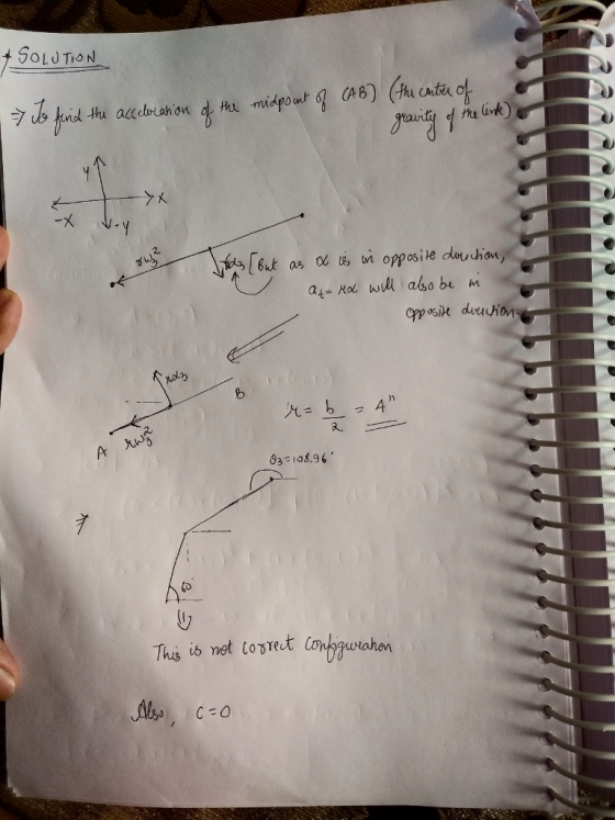
For the slider-crank arrangement shown in the figure, a-3", b - 8" and c 0. The...
QUESTION 1 A slider crank linkage is shown in figure 3 below. The angular velocity and...
 QUESTION 1 A slider crank linkage is shown in figure 3 below. The angular velocity and the angular acceleration of the crank are 10 rad/s and 40 rad/s2 respectively. Link AB is 50 mm and link BC is 95 mm. A point D on link BC is 0.2 times BC from point B Determine the following; 1.1 velocity of the piston, 1.2 angular velocity of links BC 1.3 acceleration of the piston 1.4 angular acceleration of link BC 1.5 acceleration...
The crossed four-bar linkage has a constant crank angular velocity 2=10 rad/s ccw. The dimensions and...
 The crossed four-bar linkage has a constant crank angular
velocity 2=10 rad/s ccw. The dimensions and the results of the
kinematic analysis are given below for the position shown. (a) Draw
the free-body diagrams of all the links of the mechanism, (b) Find
the reaction forces at all the pins and the driving torque at link
2. The gravity centers of link 2 and link 4 are located at O2 and
O4 respectively.
y A O2A-6 in, O204-18 in, AB-18...
The crossed four-bar linkage has a constant crank angular
velocity 2=10 rad/s ccw. The dimensions and the results of the
kinematic analysis are given below for the position shown. (a) Draw
the free-body diagrams of all the links of the mechanism, (b) Find
the reaction forces at all the pins and the driving torque at link
2. The gravity centers of link 2 and link 4 are located at O2 and
O4 respectively.
y A O2A-6 in, O204-18 in, AB-18...
3. Link 2 (AB) of the slider crank inversion shown in Figure 3 is rotating at a constant 2 11.00k(rad/s). Determine the angular velocity of link 4 (DC) at the instant shown in the figure. Hints: The...
 3. Link 2 (AB) of the slider crank inversion shown in Figure 3 is rotating at a constant 2 11.00k(rad/s). Determine the angular velocity of link 4 (DC) at the instant shown in the figure. Hints: The angle between links 3 and 4 is fized so they have the same angular velocity. Consider Cs as point on Link 3 sliding through the bearing on link 4. (100 points) C3 90° A = (0,0). Figure 3: Slider crank inversion. (110.09,0) cm....
 QUESTION 1 A slider crank linkage is shown in figure 3 below. The angular velocity and the angular acceleration of the crank are 10 rad/s and 40 rad/s2 respectively. Link AB is 50 mm and link BC is 95 mm. A point D on link BC is 0.2 times BC from point B Determine the following; 1.1 velocity of the piston, 1.2 angular velocity of links BC 1.3 acceleration of the piston 1.4 angular acceleration of link BC 1.5 acceleration...
 The crossed four-bar linkage has a constant crank angular
velocity 2=10 rad/s ccw. The dimensions and the results of the
kinematic analysis are given below for the position shown. (a) Draw
the free-body diagrams of all the links of the mechanism, (b) Find
the reaction forces at all the pins and the driving torque at link
2. The gravity centers of link 2 and link 4 are located at O2 and
O4 respectively.
y A O2A-6 in, O204-18 in, AB-18...
The crossed four-bar linkage has a constant crank angular
velocity 2=10 rad/s ccw. The dimensions and the results of the
kinematic analysis are given below for the position shown. (a) Draw
the free-body diagrams of all the links of the mechanism, (b) Find
the reaction forces at all the pins and the driving torque at link
2. The gravity centers of link 2 and link 4 are located at O2 and
O4 respectively.
y A O2A-6 in, O204-18 in, AB-18...
 3. Link 2 (AB) of the slider crank inversion shown in Figure 3 is rotating at a constant 2 11.00k(rad/s). Determine the angular velocity of link 4 (DC) at the instant shown in the figure. Hints: The angle between links 3 and 4 is fized so they have the same angular velocity. Consider Cs as point on Link 3 sliding through the bearing on link 4. (100 points) C3 90° A = (0,0). Figure 3: Slider crank inversion. (110.09,0) cm....
Most questions answered within 3 hours.
-
The average length of time between arrivals at a turnpike
toll-booth is 26 seconds. What is...
asked 1 hour ago -
(a) A piston at 6.1 atm contains a gas that occupies a volume of
3.5 L....
asked 2 hours ago -
Please answer true or false. Words
cannot be changed or added in to make it true...
asked 2 hours ago -
An empty test tube weighs 15.923 grams. Then,
MgCl2•6H2O is added into the test tube. After...
asked 2 hours ago -
Assume memory access is 10 units of time and disk access is
10000 units of time....
asked 2 hours ago -
1. Are all good samples random?
2. Magazines often report surveys giving statistics such as “63%...
asked 3 hours ago -
Under all the various types of market structures, firms
must eventually earn some economic profits for...
asked 2 hours ago -
Consider the following fitness regime for a single locus trait
with two co-dominant alleles: w11 =...
asked 3 hours ago -
A large cable company reports the following.
80% of its customers subscribe to its cable TV...
asked 3 hours ago -
Please answer the question in brief.
Discuss the role of ERP in organizations. Are ERP tools...
asked 3 hours ago -
Discuss the pros and cons of collaborative software such
as SameTime. Does it increase productivity? What...
asked 3 hours ago -
Buying your in-laws a gift because it’s expected is
due to the ____________ motive of gift-giving....
asked 3 hours ago