1. A sinusoidal current signal has amplitude of 10 amp and frequency of 60 Hz and...
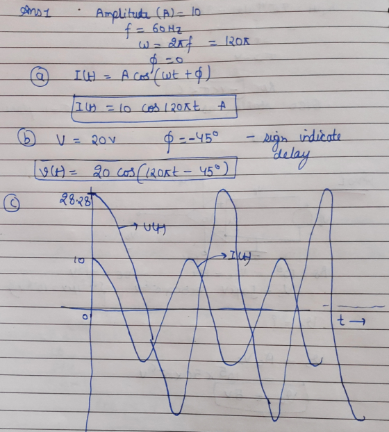
1. A sinusoidal current signal has amplitude of 10 amp and frequency of 60 Hz and phase angle of 0.
(a) Express the current in mathematical form.
(b) When it passes through an electric circuit, the voltage signal gets an amplitude of 20 volt and a phase delay of 45. Write the voltage signal.
(c) Draw both the voltage and current signals on the same graph.
2. Let a signal be defined as y(x) = (1 – x)2. Determine the following.
(a) Is the signal even or odd or have no symmetry?
(b) Find the even component of it and plot.
(c) Find the odd component of it and plot.
Homework Answers
Add Answer to:
1. A sinusoidal current signal has amplitude of 10 amp and
frequency of 60 Hz and...
2. Let a signal be defined as y(x) = (1 – x)2. Determine the following. (a)...
2. Let a signal be defined as y(x) = (1 – x)2. Determine the following. (a) Is the signal even or odd or have no symmetry? (b) Find the even component of it and plot. (c) Find the odd component of it and plot.
A 380 Hz sinusoidal voltage with a maximum amplitude of 120 V at t = 0 is applied across the terminals of an inductor.
A 380 Hz sinusoidal voltage with a maximum amplitude of 120 V at t = 0 is applied across the terminals of an inductor. The maximum amplitude of the steady-state current in the inductor is 20 A. Part A What is the frequency of the inductor current? Part B If the phase angle of the voltage is zero, what is the phase angle of the current? Part C What is the inductive reactance of the inductor? Part D What is the inductance of the inductor? Part E What is the...
Create a sinusoidal signal V(in) with the following parameters – VOFF = 10 + 2V, AMPLITUDE...
Create a sinusoidal signal V(in) with the following parameters – VOFF = 10 + 2V, AMPLITUDE = 3V, FREQUENCY= 500 Hz. Design a level shifting circuit such that the lower peak of V(in) is shifted to 5V, and the higher peak of V(in) is shifted to 0. Show by means of PSPICE Time Response simulation that your circuit really works. [Continue to use the two 9V batteries]. Make sure to explain every step in your design.
1. Sinusoidal signals The following sinusoidal diagram is the voltage across a "black box" and the...
 1. Sinusoidal signals The following sinusoidal diagram is the voltage across a "black box" and the current through it. The voltage and the current oscillate with the same frequency. a. Find the time period T, the natural frequency fand radial frequency o, Amplitude of the voltage and the current, the phase angle of the voltage and the current. (9 points) 200 current t/us t/us Current in mA lo T20 0 406 160.0 80.0 -200 20.0 voltage t/s Voltage in V...
a sinusoidal traveling transverse string wave with an amplitude of 5.5cm has a frequency of 10...
a sinusoidal traveling transverse string wave with an amplitude of 5.5cm has a frequency of 10 Hz and travels at 25m/s along the x axis.determine the maximum speed and determine the distance between the high and low spots on the string.
1-The period of oscillation of a sinusoidal signal is T=(95±3) ms. What is the uncertainty on...
1-The period of oscillation of a sinusoidal signal is T=(95±3) ms. What is the uncertainty on the frequency? (Report your value in Hz to 2 significant figures) 2-For a sinusoidal voltage waveform with amplitude A=(5.2±0.2) V, what is the error on the VRMS value? (Report your answer in V to 2 significant figures) 3-In an AC to DC rectifier circuit, the output DC signal of the rectified wave was measured to be VDC= (8.9±0.8)V and its ripple voltage was measured...
130 V. For the following problems, A 60 Hz voltage source has an amplitude of VT...
 130 V. For the following problems, A 60 Hz voltage source has an amplitude of VT compute the indicated phasors l Q1. The source is connected across a series RL ac circuit with R = 8.2 Ohm and X1 = ω k = 5.7 Ohm. 1a) Find the magnitude of impedance of the series combination (Unit: Ohm) 1b) Find the phase angle of impedance of the series combination (Unit: dea) 1c) Calculate the current phasor I at an angle of...
1) Find out the amplitude, frequency and phase displacement for given QPSK signal F(t)=100 cos(25t+π/4). 2)...
1) Find out the amplitude, frequency and phase displacement for given QPSK signal F(t)=100 cos(25t+π/4). 2) For given data incorporate with odd parity and even parity (a) 11011011 (with parity bit) (b) 1 11011011 (without parity bit)
II Review Constants Part A A 380 Hz sinusoidal voltage with a maximum amplitude of 100...
 II Review Constants Part A A 380 Hz sinusoidal voltage with a maximum amplitude of 100 V at t = 0 is applied across the terminals of an inductor. The maximum amplitude of the steady-state current in the inductor is 10 A. What is the frequency of the inductor current? Express your answer with the appropriate units. GÅ N O 2 ? f= Value Units Submit Request Answer Part B If the phase angle of the voltage is zero, what...
2. Given the voltage waveform in Figure. a). What is the frequency of the signal? b).What...
 2. Given the voltage waveform in Figure. a). What is the frequency of the signal? b).What is the phase shift of the waveform? c) What is the maximum amplitude of the AC signal? d). What is the sine function that describes the waveform? e). What is the cosine function that describes the waveform? * Plot of a sinusoidal signal Magnitude -15 --20 -25 0.00 0.02 0.04 0.06 0.08 0.10 0.12 0.14 Time (ms) Figure P4.1 AC Signal to be Analyzed...
 1. Sinusoidal signals The following sinusoidal diagram is the voltage across a "black box" and the current through it. The voltage and the current oscillate with the same frequency. a. Find the time period T, the natural frequency fand radial frequency o, Amplitude of the voltage and the current, the phase angle of the voltage and the current. (9 points) 200 current t/us t/us Current in mA lo T20 0 406 160.0 80.0 -200 20.0 voltage t/s Voltage in V...
 130 V. For the following problems, A 60 Hz voltage source has an amplitude of VT compute the indicated phasors l Q1. The source is connected across a series RL ac circuit with R = 8.2 Ohm and X1 = ω k = 5.7 Ohm. 1a) Find the magnitude of impedance of the series combination (Unit: Ohm) 1b) Find the phase angle of impedance of the series combination (Unit: dea) 1c) Calculate the current phasor I at an angle of...
 II Review Constants Part A A 380 Hz sinusoidal voltage with a maximum amplitude of 100 V at t = 0 is applied across the terminals of an inductor. The maximum amplitude of the steady-state current in the inductor is 10 A. What is the frequency of the inductor current? Express your answer with the appropriate units. GÅ N O 2 ? f= Value Units Submit Request Answer Part B If the phase angle of the voltage is zero, what...
 2. Given the voltage waveform in Figure. a). What is the frequency of the signal? b).What is the phase shift of the waveform? c) What is the maximum amplitude of the AC signal? d). What is the sine function that describes the waveform? e). What is the cosine function that describes the waveform? * Plot of a sinusoidal signal Magnitude -15 --20 -25 0.00 0.02 0.04 0.06 0.08 0.10 0.12 0.14 Time (ms) Figure P4.1 AC Signal to be Analyzed...
Most questions answered within 3 hours.
-
Mark Gershon, owner of a musical instrument distributorship,
thinks that demand for guitars may be related...
asked 9 minutes ago -
Suppose that you were asked to construct a 95% confidence
interval based on the standard normal...
asked 16 minutes ago -
3 - What decimal number does the bit pattern 11001100 represent
if it is a:
•...
asked 18 minutes ago -
The copper(II) ion is acidic whereas the acetate ion is basic.
However, copper acetate is acidic....
asked 14 minutes ago -
A 48.53 mL volume of 1.00 M HCl was mixed with 47.70 mL of 2.00
M...
asked 36 minutes ago -
Neural cell types can be specified from ESCs with
retinoic acid, conditioned medium, co-cultures or by...
asked 40 minutes ago -
Can anyone solve: "Simulation with Arena 6th Edition - Chapter 8
- Question 3E"
8-3 Change...
asked 37 minutes ago -
What are some issues related to crimes, victims &
victimization that should be addressed?
asked 44 minutes ago -
Water flowing uniformly in a rectangular open channel has
manning value of 0.017, bottom slope of...
asked 1 hour ago -
Nature Conservancy's leader abruptly steps
down.
One morning in October 2007, Steven. J. McCormick the president...
asked 1 hour ago -
I asked a question similar to this one, which was answered
perfectly. Another practice problem is...
asked 1 hour ago -
Rachel is studying cholesterol synthesis in mice. Some mice
had a mutation in their sterol regulatory...
asked 1 hour ago