
Homework Answers

Add Answer to:
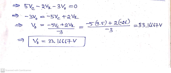
Question 2 25 pts Determine the output voltage Vo of the circuit shown below. Given Vin...
Determine the output voltage Vo of the circuit shown below. Given Vin = 15V V2 =...
 Determine the output voltage Vo of the circuit shown below. Given Vin = 15V V2 = 6V and R = 4412 Treat the nodes labeled Vin and V2 as if they are connected to sources. 2R R 2R Vin 3R + R OV R V20w
Determine the gain Vo/Vin of the circuit shown below. Given Vin = 14V V2 = 5V...
 Determine the gain Vo/Vin of the circuit shown below. Given Vin = 14V V2 = 5V and R= 2012 Treat the nodes labeled Vin and V2 as if they are connected to sources. 2R W Vino R WWW 2R WWW 3R w R OV, w R V20
Determine the output voltage Vo of the circuit shown below. Given Vs = 6V Rs1 =...
 Determine the output voltage Vo of the circuit shown below. Given Vs = 6V Rs1 = 622 RF1 = 51 Rs2 = 31 RF2 = 912 REI Rsi RF2 ww RS2 + Vo VS 오
1. Find the ratio of the output voltage to the input voltage, Vo/Vin, in the circuit...
 1. Find the ratio of the output voltage to the input voltage, Vo/Vin, in the circuit shown. State your assumptions in using the ideal op-amp model. 15 k2 Vin 2. Find the output voltage Vo in the circuit shown assuming an ideal op-amp. State your assumptions in using the ideal op-amp model 15 k12 Vo . Find the voltage Vx and the output voltage Vo in the circuit shown assuming ideal op-amp 3 k2 1 V 6 kn 12 k2
Problem 1130 pts 1. [12 pts] For the circuit shown in Fig. 1, istance Rm when the switch is open. What type of voltage gain Vo/Vin and the input resistance Rin when the switch is close. What type of...
 Problem 1130 pts 1. [12 pts] For the circuit shown in Fig. 1, istance Rm when the switch is open. What type of voltage gain Vo/Vin and the input resistance Rin when the switch is close. What type of a) Find the voltage gain val vin and the input resistance Rin when the switch is open b) Find the amplifier is this? amplifier is this? tin vo R Fig. 1 [18 pts] Design a circuit that implements the following: Vo(t)...
Question 2 2. Determine the output voltage Vo of the circuit shown below. Given Vs =...
 Question 2 2. Determine the output voltage Vo of the circuit shown below. Given Vs = 9V Rs1 = 101 RF1 = 522 Rs2 = 1022 RF2=512 RFI RSI RF2 RS2
A MOSFET is wired as a common-source amplifier as shown below. The input voltage vIN is...
 A MOSFET is wired as a common-source amplifier as shown below.
The input voltage vIN is the total of the source for
biasing the circuit at its operating point (vBIAS), and
a small signal ac source providing the signal that we want to
amplify (vin). The total output voltage is
vO.
a) Assume VDD = 5?, VIN = 2?, and ? = 4?Ω
in the circuit and the MOSFET parameters are K =
0.5??/?2, VTH 1?, and ? = 0.05V-1....
A MOSFET is wired as a common-source amplifier as shown below.
The input voltage vIN is the total of the source for
biasing the circuit at its operating point (vBIAS), and
a small signal ac source providing the signal that we want to
amplify (vin). The total output voltage is
vO.
a) Assume VDD = 5?, VIN = 2?, and ? = 4?Ω
in the circuit and the MOSFET parameters are K =
0.5??/?2, VTH 1?, and ? = 0.05V-1....
The circuit below implements a current-to-voltage convertor. Show that the output voltage, vo, is given by R1 R3 R, R,...
 The circuit below implements a current-to-voltage convertor. Show that the output voltage, vo, is given by R1 R3 R, R, R2
The circuit below implements a current-to-voltage convertor. Show that the output voltage, vo, is given by R1 R3 R, R, R2
The circuit below implements a current-to-voltage convertor. Show that the output voltage, vo, is given by R1 R3 R, R, R2
In the circuit shown below, R1 1. Find output voltage Vo. 2. Find I1, 12, and...
 In the circuit shown below, R1 1. Find output voltage Vo. 2. Find I1, 12, and Ip. 0.7V and Vps5V R2 1000, Vp R1 Vo w R2 VPs
For the circuit shown in figure 1, determine the range of the output voltage Vo.
 For the circuit shown in figure 1, determine the range of the output voltage Vo.
 Determine the output voltage Vo of the circuit shown below. Given Vin = 15V V2 = 6V and R = 4412 Treat the nodes labeled Vin and V2 as if they are connected to sources. 2R R 2R Vin 3R + R OV R V20w
 Determine the gain Vo/Vin of the circuit shown below. Given Vin = 14V V2 = 5V and R= 2012 Treat the nodes labeled Vin and V2 as if they are connected to sources. 2R W Vino R WWW 2R WWW 3R w R OV, w R V20
 Determine the output voltage Vo of the circuit shown below. Given Vs = 6V Rs1 = 622 RF1 = 51 Rs2 = 31 RF2 = 912 REI Rsi RF2 ww RS2 + Vo VS 오
 1. Find the ratio of the output voltage to the input voltage, Vo/Vin, in the circuit shown. State your assumptions in using the ideal op-amp model. 15 k2 Vin 2. Find the output voltage Vo in the circuit shown assuming an ideal op-amp. State your assumptions in using the ideal op-amp model 15 k12 Vo . Find the voltage Vx and the output voltage Vo in the circuit shown assuming ideal op-amp 3 k2 1 V 6 kn 12 k2
 Problem 1130 pts 1. [12 pts] For the circuit shown in Fig. 1, istance Rm when the switch is open. What type of voltage gain Vo/Vin and the input resistance Rin when the switch is close. What type of a) Find the voltage gain val vin and the input resistance Rin when the switch is open b) Find the amplifier is this? amplifier is this? tin vo R Fig. 1 [18 pts] Design a circuit that implements the following: Vo(t)...
 Question 2 2. Determine the output voltage Vo of the circuit shown below. Given Vs = 9V Rs1 = 101 RF1 = 522 Rs2 = 1022 RF2=512 RFI RSI RF2 RS2
 A MOSFET is wired as a common-source amplifier as shown below.
The input voltage vIN is the total of the source for
biasing the circuit at its operating point (vBIAS), and
a small signal ac source providing the signal that we want to
amplify (vin). The total output voltage is
vO.
a) Assume VDD = 5?, VIN = 2?, and ? = 4?Ω
in the circuit and the MOSFET parameters are K =
0.5??/?2, VTH 1?, and ? = 0.05V-1....
A MOSFET is wired as a common-source amplifier as shown below.
The input voltage vIN is the total of the source for
biasing the circuit at its operating point (vBIAS), and
a small signal ac source providing the signal that we want to
amplify (vin). The total output voltage is
vO.
a) Assume VDD = 5?, VIN = 2?, and ? = 4?Ω
in the circuit and the MOSFET parameters are K =
0.5??/?2, VTH 1?, and ? = 0.05V-1....
 The circuit below implements a current-to-voltage convertor. Show that the output voltage, vo, is given by R1 R3 R, R, R2
The circuit below implements a current-to-voltage convertor. Show that the output voltage, vo, is given by R1 R3 R, R, R2
The circuit below implements a current-to-voltage convertor. Show that the output voltage, vo, is given by R1 R3 R, R, R2
 In the circuit shown below, R1 1. Find output voltage Vo. 2. Find I1, 12, and Ip. 0.7V and Vps5V R2 1000, Vp R1 Vo w R2 VPs
Most questions answered within 3 hours.
-
Having conducted the ethics audit, identify the formal and
informal systems that are in need of...
asked 26 minutes ago -
1)a. Using the Born Haber cycle, determine the enthalpy for
lattice formation of MgO.
Mg (s),...
asked 51 minutes ago -
6. The Bill of Rights (first 10 Amendments to the US
Constitution) consists of several limitations...
asked 47 minutes ago -
What are the ethical issue of using robotics in surgery ? List
the issues based on...
asked 1 hour ago -
URGENT
1. A person standing a certain distance from nine identical
loudspeakers is hearing a sound...
asked 1 hour ago -
If X1 ∼ χ21 and
X2 ∼ χ21 , then? show your
work.
(a) X1 + X2...
asked 1 hour ago -
a fair red die and a fair blue die are rolled. What is the
expected value...
asked 2 hours ago -
How many unpaired electrons would you expect for the complex ion
[FeF6]4-?
0
2
6
3...
asked 2 hours ago -
please briefly explain your idea about the following
paragraph.
Genetic engineering is a process of modifying...
asked 2 hours ago -
When a piece of wood is pressed against a spring and compresses
the spring by 2.00...
asked 2 hours ago -
Organizations that interact with medical patients are subject to
HIPAA compliance.
a. Briefly describe, in your...
asked 4 hours ago -
1. A sociologist examines the relationship between the poverty
rate and several socioeconomic factors. For the...
asked 5 hours ago