
Homework Answers

Please forgive me for any calculation mistake and do comment for any short of queries.
Add Answer to:
The following is the torque versus angle of twist diagram for a 0.75 inch diameter steel...
The following is the torque versus angle of twist diagram for a 0.75 inch diameter steel...
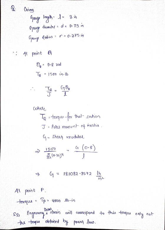
 The following is the torque versus angle of twist diagram for a 0.75 inch diameter steel bar tested in torsion. The gage length of the bar is 3 inches. The angle of rotation and torque at points Q and P are (0.8 radian, 1500 in-lb) and (11.3 radian, 4000 in-lb) respectively. The power-law curve fitting relation for the data above the yield point is given by T = 329880.21, where T is in in-lb and e is in radian. Torque...
The following is the torque versus angle of twist diagram for a 0.75 inch diameter steel...
 The following is the torque versus angle of twist diagram for a 0.75 inch diameter steel bar tested in torsion. The gage length of the bar is 3 inches. The angle of rotation and torque at points Q and P are (0.8 radian, 1500 in-lb) and (11.3 radian, 4000 in-lb) respectively. The power-law curve fitting relation for the data above the yield point is given by T = 329880.21, where T is in in-lb and g is in radian. Torque...
Question 19 1 points Save Answer The following is the torque versus angle of twist diagram...
 Question 19 1 points Save Answer The following is the torque versus angle of twist diagram for a 0.75 inch diameter steel bar tested in torsion. The gage length of the bar is 3 inches. The angle of rotation and torque at points Q and Pare (0.8 radian, 1500 in-Ib) and (11.3 radian, 4000 in-Ib) respectively. The power-law curve fitting relation for the data above the yield point is given by T=329880.21, where T is in in-Ib and 2 is...
The following is the torque versus angle of twist diagram for a 0.75 inch diameter steel...
 The following is the torque versus angle of twist diagram for a 0.75 inch diameter steel bar tested in torsion. The gage length of the bar is 3 inches. The angle of rotation and torque at points Q and P are (0.8 radian, 1500 in-lb) and (11.3 radian, 4000 in-lb) respectively. The power-law curve fitting relation for the data above the yield point is given by T = 329880.21, where T is in in-lb and e is in radian. Torque...
Question 20 1 points Saved The following is the torque versus angle of twist diagram for...
 Question 20 1 points Saved The following is the torque versus angle of twist diagram for a 0.75 inch diameter steel bar tested in torsion. The gage length of the bar is 3 inches. The angle of rotation and torque at points and Pare (0.8 radian, 1500 in-Ib) and (11.3 radian, 4000 in-lb) respectively. The power-law curve fitting relation for the data above the yield point is given by T-329800.21, where is in in-Ib and is in radian. Torque T...
Saved Question 20 1 points The following is the torque versus angle of twist diagram for...
 Saved Question 20 1 points The following is the torque versus angle of twist diagram for a 0.75 inch diameter steel bar tested in torsion. The gage length of the bar is 3 inches. The angle of rotation and torque at points and Pare (0.8 radian, 1500 in-lb) and (11.3 radian, 4000 in-Ib) respectively. The power-law curve fitting relation for the data above the yield point is given by T-32980021, where T is in in-lb and is in radian Torque...
1. The following is a one-layer truss structure fabricated from aluminum tubing with outside diameter and...
 1. The following is a one-layer truss structure fabricated from aluminum tubing with outside diameter and wall thickness as 0.4 inch and 0.05 inch, respectively. The Young's modulus and Poisson's ratio for aluminum are E= 10 x 10°psi, v=0.33, respectively. The applied load P is 60 Ib. Please answer = 60° B Ra all Cled URb The internal force for member AC is: -30 lb 34.6 lb 30 lb -34.6 lb Question 2 1 points Save Answer 1. The following...
 The following is the torque versus angle of twist diagram for a 0.75 inch diameter steel bar tested in torsion. The gage length of the bar is 3 inches. The angle of rotation and torque at points Q and P are (0.8 radian, 1500 in-lb) and (11.3 radian, 4000 in-lb) respectively. The power-law curve fitting relation for the data above the yield point is given by T = 329880.21, where T is in in-lb and e is in radian. Torque...
 The following is the torque versus angle of twist diagram for a 0.75 inch diameter steel bar tested in torsion. The gage length of the bar is 3 inches. The angle of rotation and torque at points Q and P are (0.8 radian, 1500 in-lb) and (11.3 radian, 4000 in-lb) respectively. The power-law curve fitting relation for the data above the yield point is given by T = 329880.21, where T is in in-lb and g is in radian. Torque...
 The following is the torque versus angle of twist diagram for a 0.75 inch diameter steel bar tested in torsion. The gage length of the bar is 3 inches. The angle of rotation and torque at points Q and P are (0.8 radian, 1500 in-lb) and (11.3 radian, 4000 in-lb) respectively. The power-law curve fitting relation for the data above the yield point is given by T = 329880.21, where T is in in-lb and g is in radian. Torque...
 The following is the torque versus angle of twist diagram for a 0.75 inch diameter steel bar tested in torsion. The gage length of the bar is 3 inches. The angle of rotation and torque at points Q and P are (0.8 radian, 1500 in-lb) and (11.3 radian, 4000 in-lb) respectively. The power-law curve fitting relation for the data above the yield point is given by T = 329880.21, where T is in in-lb and g is in radian. Torque...
 Question 19 1 points Save Answer The following is the torque versus angle of twist diagram for a 0.75 inch diameter steel bar tested in torsion. The gage length of the bar is 3 inches. The angle of rotation and torque at points Q and Pare (0.8 radian, 1500 in-Ib) and (11.3 radian, 4000 in-Ib) respectively. The power-law curve fitting relation for the data above the yield point is given by T=329880.21, where T is in in-Ib and 2 is...
 The following is the torque versus angle of twist diagram for a 0.75 inch diameter steel bar tested in torsion. The gage length of the bar is 3 inches. The angle of rotation and torque at points Q and P are (0.8 radian, 1500 in-lb) and (11.3 radian, 4000 in-lb) respectively. The power-law curve fitting relation for the data above the yield point is given by T = 329880.21, where T is in in-lb and e is in radian. Torque...
 Question 20 1 points Saved The following is the torque versus angle of twist diagram for a 0.75 inch diameter steel bar tested in torsion. The gage length of the bar is 3 inches. The angle of rotation and torque at points and Pare (0.8 radian, 1500 in-Ib) and (11.3 radian, 4000 in-lb) respectively. The power-law curve fitting relation for the data above the yield point is given by T-329800.21, where is in in-Ib and is in radian. Torque T...
 Saved Question 20 1 points The following is the torque versus angle of twist diagram for a 0.75 inch diameter steel bar tested in torsion. The gage length of the bar is 3 inches. The angle of rotation and torque at points and Pare (0.8 radian, 1500 in-lb) and (11.3 radian, 4000 in-Ib) respectively. The power-law curve fitting relation for the data above the yield point is given by T-32980021, where T is in in-lb and is in radian Torque...
 1. The following is a one-layer truss structure fabricated from aluminum tubing with outside diameter and wall thickness as 0.4 inch and 0.05 inch, respectively. The Young's modulus and Poisson's ratio for aluminum are E= 10 x 10°psi, v=0.33, respectively. The applied load P is 60 Ib. Please answer = 60° B Ra all Cled URb The internal force for member AC is: -30 lb 34.6 lb 30 lb -34.6 lb Question 2 1 points Save Answer 1. The following...
Most questions answered within 3 hours.
-
Railco sells to its customers on account with terms of 2% / 5
/net 15. Ronco...
asked 2 minutes ago -
Refer to the following lease amortization schedule. The 10
payments are made annually starting with the...
asked 16 minutes ago -
Explain how God fits into Aquinas' theory of happiness.
asked 24 minutes ago -
1.1 With aid of diagrams and suitable examples discuss
the economic effects of price controls.
1.2...
asked 29 minutes ago -
When the nuclide polonium-214 undergoes alpha
decay:
The name of the product nuclide is .
The...
asked 43 minutes ago -
Q. The market demand function is D(Pd) = 160 - 2Pd and the
market supply function...
asked 48 minutes ago -
An unknown alcohol is analyzed by freezing point depression. The
unknown is either methanol (CH3OH), ethanol...
asked 49 minutes ago -
As a person inhales, air moves down the windpipe (bronchus),
through a constriction where the air...
asked 51 minutes ago -
Youngchang Keyboard sells a $1400 keyboard on a monthly payment
plan over 2 years.
a) If...
asked 57 minutes ago -
For a one step reaction, the activation energy for the
forward reaction is 40.0 kJ mol-1,...
asked 1 hour ago -
1. A good thesis statement _____ .
is limited but not too narrow
is very broad...
asked 56 minutes ago -
What is the main use of a transistor and what is an Integrated
Circuit?
asked 1 hour ago