
Homework Answers
Add Answer to:
A beam whose cross-section is shown in the figure is subjected to a bending moment M...
2) A box beam of rectangular cross section shown is subject to a bending moment Mx=2000...
 2) A box beam of rectangular cross section shown is subject to a bending moment Mx=2000 lb in. Find the maximum tensile stress and maximum compressive stress and their respective locations. What is the orientation of the neutral axis? 0.064" 12" 0.04" ... . M. 0.072 0.03"
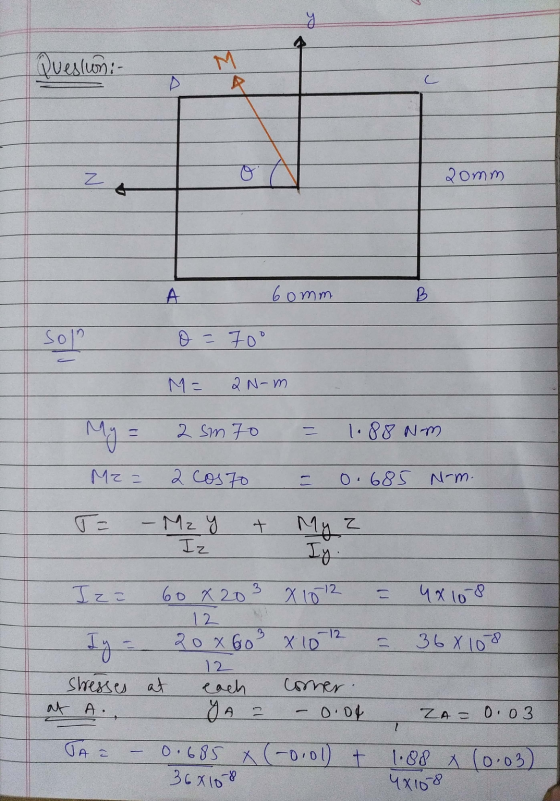
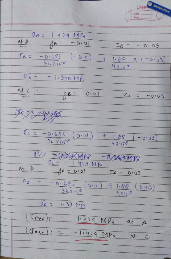
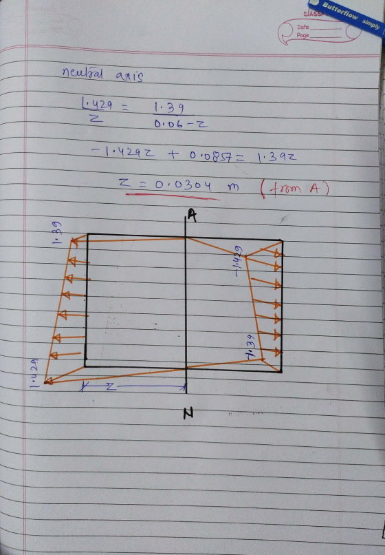
Problem 2 A T-beam is subjected to a moment M at the orientation shown: M? 150...
 Problem 2 A T-beam is subjected to a moment M at the orientation shown: M? 150 mm 50 mm Determine the orientation of the neutral axis measured from the positive z-axis. a) b) Determine the maximum value of M if the allowable tensile stress is 10 MPa and the allowable compressive stress is 7 MPa. 200 mm C
A beam having the cross-section shown below is subjected to a bending moment of 1500 Nm...
 A beam having the cross-section shown below is subjected to a bending moment of 1500 Nm in x-axis. Calculate the maximum direct stress due to bending and state the point at which it acts. 40 mm 80 mm у B 8 mm C IX x 80 mm ΕΙ 8 mm
If the beam, shown in Figure 6, is subjected to an internal moment of 2.5 kNm,...
 If the beam, shown in Figure 6, is subjected to an internal moment of 2.5 kNm, determine the maximum tensile and compressive stress in the beam. Also sketch the bending stress distribution on the cross section.
3. The beam, with symmetric cross-section about y (all thicknesses of 1 in) as shown, is...
 3. The beam, with symmetric cross-section about y (all thicknesses of 1 in) as shown, is subjected to an internal moment of M 480 kip.in and a shear force of V 340 kip. For this system, a) determine the location of the neutral axis, y (measured from the bottom of cross-section as shown) and the area moment of inertia, I about the neutral axis (NA or z-axis), the maximum compressive, (o,nax), and tensile, (Omax): normal stresses, and b) o kip....
3) (35 pts) A L-beam has the cross section shown. A moment M acts about the...
 3) (35 pts) A L-beam has the cross section shown. A moment M acts about the x-axis which passes through the centroid of the section. Determine the angle the neutral axis makes with respect to axis. Sketch it on the cross section. Given the design flexural stress limit is 100 MPa, determine the maximum allowable moment which can be applied. You only need to evaluate the stresses at points A, B. Helpful hint: Remember to change the sign of your...
If the beam is subjected to a moment of M = 100 kn-m, determine the bending stress at points A, B, and C.
 If the beam is subjected to a moment of M = 100 kn-m, determine the bending stress at points A, B, and C. Sketch the bending stress distribution on the cross Section. If the beam is made of a material having an allowable tensile and compressive stress of σallow(T) = 125 MPa and σallow(C) = 150 MPa, respectively, determine the maximum moment M that can be applied to the beam.
The beam is subjected to a moment of M = 4.8kip·ft . (Figure 1)
 The beam is subjected to a moment of M = 4.8kip·ft . (Figure 1) Part ADetermine the maximum tensile bending stress in the beam. Part B Determine the maximum compressive bending stress in the beam.
3) (35 pts) A L-beam has the cross section shown. A moment M acts about the...
 3) (35 pts) A L-beam has the cross section shown. A moment M acts about the x-axis which passes through the centroid of the section. Determine the angle the neutral axis makes with respect to the +x- axis. Sketch it on the cross section. Given the design flexural stress limit is 100 MPa, determine the maximum allowable moment which can be applied. You only need to evaluate the stresses at points A, 8. Helpful hint: Remember to change the sign...
 2) A box beam of rectangular cross section shown is subject to a bending moment Mx=2000 lb in. Find the maximum tensile stress and maximum compressive stress and their respective locations. What is the orientation of the neutral axis? 0.064" 12" 0.04" ... . M. 0.072 0.03"
 Problem 2 A T-beam is subjected to a moment M at the orientation shown: M? 150 mm 50 mm Determine the orientation of the neutral axis measured from the positive z-axis. a) b) Determine the maximum value of M if the allowable tensile stress is 10 MPa and the allowable compressive stress is 7 MPa. 200 mm C
 A beam having the cross-section shown below is subjected to a bending moment of 1500 Nm in x-axis. Calculate the maximum direct stress due to bending and state the point at which it acts. 40 mm 80 mm у B 8 mm C IX x 80 mm ΕΙ 8 mm
 If the beam, shown in Figure 6, is subjected to an internal moment of 2.5 kNm, determine the maximum tensile and compressive stress in the beam. Also sketch the bending stress distribution on the cross section.
 3. The beam, with symmetric cross-section about y (all thicknesses of 1 in) as shown, is subjected to an internal moment of M 480 kip.in and a shear force of V 340 kip. For this system, a) determine the location of the neutral axis, y (measured from the bottom of cross-section as shown) and the area moment of inertia, I about the neutral axis (NA or z-axis), the maximum compressive, (o,nax), and tensile, (Omax): normal stresses, and b) o kip....
 3) (35 pts) A L-beam has the cross section shown. A moment M acts about the x-axis which passes through the centroid of the section. Determine the angle the neutral axis makes with respect to axis. Sketch it on the cross section. Given the design flexural stress limit is 100 MPa, determine the maximum allowable moment which can be applied. You only need to evaluate the stresses at points A, B. Helpful hint: Remember to change the sign of your...
 3) (35 pts) A L-beam has the cross section shown. A moment M acts about the x-axis which passes through the centroid of the section. Determine the angle the neutral axis makes with respect to the +x- axis. Sketch it on the cross section. Given the design flexural stress limit is 100 MPa, determine the maximum allowable moment which can be applied. You only need to evaluate the stresses at points A, 8. Helpful hint: Remember to change the sign...
Most questions answered within 3 hours.
-
Cynaide is a deadly poison that blocks the last step in the
electron transport chain of...
asked 49 seconds from now -
Your friend tells you that there is a vending machine on campus
that dispenses M&M packs...
asked 14 minutes ago -
What advantages are there to using piperidine rather than
hydroxide as a base?
asked 12 minutes ago -
7. The life of a Freeze Breeze electric fan is normally
distributed with a mean 4...
asked 15 minutes ago -
1. A 751 mL NaCl solution is diluted to a volume of 1.06 L and a...
asked 20 minutes ago -
8
A $20,000 face value STRIPS is currently quoted at 38.642 and
has 8 years to...
asked 21 minutes ago -
The current exchange rate between the Japanese yen and
the US dollar is 120 yen per...
asked 23 minutes ago -
Marla’s Massages and More bought a special massage table two
years ago for $9,300. At the...
asked 30 minutes ago -
Suppose you require a peak output voltage of 15.0 V and have
available an AC source...
asked 30 minutes ago -
We
conduct A study to estimate the mean age of the population of women
at the...
asked 41 minutes ago -
.13 : Assume that we make an enhancement to a computer that
improves some mode of...
asked 43 minutes ago -
4)
Find the tension in an elevator cable if the 1000 kg elevator is
descending with...
asked 49 minutes ago