I am currently trying to figure out the experiment below. Please complete Table 1 with an explanation, I appreciate it thank you! Promise to give thumbs up!


Homework Answers
here is the answer:-
 =
360
=
360  (
(  ) = 360
(
) = 360
( )
) =
=
for resonance:-
L
= 360
(
VL)
= 360
(7.8810-6)(30700)
= 87.08
C=360
(
VC)
= 360
(-7.8110-6)(30700)
= -86.31
tot
=360
(
Vo)
= 360
(0)
(30700) = 0
| system | frequency |
VL |
VC |
Vo |
 |
 |
 |
|---|---|---|---|---|---|---|---|
| Resonance | 30700 | 7.88 | -7.81 | 0.00 | 87.08 | -86.31 | 0 |
| below resonance | 18700 | 12.50 | -12.80 | -6.97 | 84.15 | -86.16 | -47.92 |
| Above resonance | 48700 | 5.10 | -4.94 | 2.77 | 89.41 | -86.61 | 48.56 |
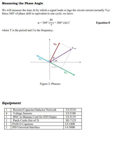
please have a look that in
tot do we have to make addition of
L and
C or we have to take
Vo for calculations as taken here.
thank you.
Add Answer to:
I am currently trying to figure out the experiment below. Please
complete Table 1 with an...
An AC generator supplies an rms voltage of 120 V at 60.0 Hz. It is connected...
An AC generator supplies an rms voltage of 120 V at 60.0 Hz. It is connected in series with a 0.450 H inductor, a 5.4 uF capacitor and a 351 ohm resistor. What is the impedance of the circuit? What is the rms current through the resistor? What is the average power dissipated in the circuit? What is the peak current through the resistor? What is the peak voltage across the inductor? What is the peak voltage across the capacitor?...
An AC generator supplies an rms voltage of 120 V at 60.0 Hz. It is connected...
An AC generator supplies an rms voltage of 120 V at 60.0 Hz. It is connected in series with a 0.400 H inductor, a 5.30 ?F capacitor and a 251 ohm resistor. A.) What is the impedance of the circuit? B.) What is the rms current through the resistor? C.) What is the average power dissipated in the circuit? D.) What is the peak current through the resistor? E.) What is the peak voltage across the inductor F.) What is...
An AC generator supplies an rms voltage of 120 V at 60.0 Hz. It is connected...
An AC generator supplies an rms voltage of 120 V at 60.0 Hz. It is connected in series with a 0.350 H inductor, a 5.10 μF capacitor and a 306 Ω resistor. a. What is the impedance of the circuit? b. What is the rms current through the resistor? c. What is the average power dissipated in the circuit? d. What is the peak current through the resistor? e. What is the peak voltage across the inductor? f. What is...
Question 2- An alternating current power supply is connected as shown in the figure to a...
 Question 2- An alternating current power supply is connected as shown in the figure to a resistor, a capacitor, and an inductor. The power supply provides a voltage given by ε(t)-fo . cos(ωt). a) Make a phasor diagram and draw the voltage and current phasors for the resistor, capacitor, and inductor. (Be sure the phase relations between each phasor is clear, and be sure to label all phasors.) b) Use your diagram to find an equation for lo (the amplitude...
8–31 A voltage vs(t) = 50 cos (5000t) V is applied to the circuit in Figure...
 8–31 A voltage vs(t) = 50 cos (5000t) V is applied to the circuit in Figure P8–31. (a) Convert the circuit into the phasor domain. (b) Find the phasor current flowing through the circuit and the phasor voltages across the inductor and the resistor. (c) Plot all three phasors from (b) on a phasor diagram. Describe if the current leads or lags the inductor voltage. i(t) 50 22 25 mH 00 + VL(t) - + Vr(t)- vs(t) (+) FIGURE P8-31
130 V. For the following problems, A 60 Hz voltage source has an amplitude of VT...
 130 V. For the following problems, A 60 Hz voltage source has an amplitude of VT compute the indicated phasors l Q1. The source is connected across a series RL ac circuit with R = 8.2 Ohm and X1 = ω k = 5.7 Ohm. 1a) Find the magnitude of impedance of the series combination (Unit: Ohm) 1b) Find the phase angle of impedance of the series combination (Unit: dea) 1c) Calculate the current phasor I at an angle of...
An AC generator supplies an rms voltage of 110 V at 60.0 Hz. It is connected...
 An AC generator supplies an rms voltage of 110 V at 60.0 Hz. It is connected in series with a 0.300 H inductor, a 5.60 uF capacitor and a 256 2 resistor. What is the impedance of the circuit? Submit Answer Tries 0/20 What is the rms current through the resistor? Submit Answer Tries 0/20 What is the average power dissipated in the circuit? Submit Answer Tries 0/20 What is the peak current through the resistor? Submit Answer Tries 0/20...
(2 points) Two driven inductors A R = 1 kΩ resistor, a L1 = 20 mH...
 (2 points) Two driven inductors A R = 1 kΩ resistor, a L1 = 20 mH inductor and a L2 28 mH inductor are connected in series. A funtion generator drives the circuit with a 5 Vpp variable frequency sine wave. (a) What is the equivalent impedance Zeq of this circuit? O A. R +jwLIL2/(L1+ L2) E. None of these (b) For what angular frequency does |Zoq v2 R? 20833.3 radians/sec (c) What is the peak-to-peak value of the voltage...
In a series R-L-C circuit, L = 0.190 H , C = 84.5 μF and the...
In a series R-L-C circuit, L = 0.190 H , C = 84.5 μF and the voltage amplitude of the source is 290 V . Part A What is the resonance angular frequency of the circuit? ω0 = rad/s SubmitMy AnswersGive Up Part B When the source operates at the resonance angular frequency, the current amplitude in the circuit is 0.610 A . What is the resistance R of the resistor? R = Ω SubmitMy AnswersGive Up Part C At...
please help, if you're able to explain a-f that would be great, but i mainly need...
 please help, if you're able to explain a-f that would be great, but
i mainly need help with G
<Ch31. AC Circuits Part Part A Exercise 31.12 - Enhanced - with Feedback What is the impedance of the circuit? Express your answer with the appropriate units. What is the voltage amplitude across the resistor? Express your answer with the appropriate units. 2 = 251 VR = 19.7V Previous Answers Sube Previous Answers You have a 170 resistor, a 0.800 H...
please help, if you're able to explain a-f that would be great, but
i mainly need help with G
<Ch31. AC Circuits Part Part A Exercise 31.12 - Enhanced - with Feedback What is the impedance of the circuit? Express your answer with the appropriate units. What is the voltage amplitude across the resistor? Express your answer with the appropriate units. 2 = 251 VR = 19.7V Previous Answers Sube Previous Answers You have a 170 resistor, a 0.800 H...
 Question 2- An alternating current power supply is connected as shown in the figure to a resistor, a capacitor, and an inductor. The power supply provides a voltage given by ε(t)-fo . cos(ωt). a) Make a phasor diagram and draw the voltage and current phasors for the resistor, capacitor, and inductor. (Be sure the phase relations between each phasor is clear, and be sure to label all phasors.) b) Use your diagram to find an equation for lo (the amplitude...
 8–31 A voltage vs(t) = 50 cos (5000t) V is applied to the circuit in Figure P8–31. (a) Convert the circuit into the phasor domain. (b) Find the phasor current flowing through the circuit and the phasor voltages across the inductor and the resistor. (c) Plot all three phasors from (b) on a phasor diagram. Describe if the current leads or lags the inductor voltage. i(t) 50 22 25 mH 00 + VL(t) - + Vr(t)- vs(t) (+) FIGURE P8-31
 130 V. For the following problems, A 60 Hz voltage source has an amplitude of VT compute the indicated phasors l Q1. The source is connected across a series RL ac circuit with R = 8.2 Ohm and X1 = ω k = 5.7 Ohm. 1a) Find the magnitude of impedance of the series combination (Unit: Ohm) 1b) Find the phase angle of impedance of the series combination (Unit: dea) 1c) Calculate the current phasor I at an angle of...
 An AC generator supplies an rms voltage of 110 V at 60.0 Hz. It is connected in series with a 0.300 H inductor, a 5.60 uF capacitor and a 256 2 resistor. What is the impedance of the circuit? Submit Answer Tries 0/20 What is the rms current through the resistor? Submit Answer Tries 0/20 What is the average power dissipated in the circuit? Submit Answer Tries 0/20 What is the peak current through the resistor? Submit Answer Tries 0/20...
 (2 points) Two driven inductors A R = 1 kΩ resistor, a L1 = 20 mH inductor and a L2 28 mH inductor are connected in series. A funtion generator drives the circuit with a 5 Vpp variable frequency sine wave. (a) What is the equivalent impedance Zeq of this circuit? O A. R +jwLIL2/(L1+ L2) E. None of these (b) For what angular frequency does |Zoq v2 R? 20833.3 radians/sec (c) What is the peak-to-peak value of the voltage...
 please help, if you're able to explain a-f that would be great, but
i mainly need help with G
<Ch31. AC Circuits Part Part A Exercise 31.12 - Enhanced - with Feedback What is the impedance of the circuit? Express your answer with the appropriate units. What is the voltage amplitude across the resistor? Express your answer with the appropriate units. 2 = 251 VR = 19.7V Previous Answers Sube Previous Answers You have a 170 resistor, a 0.800 H...
please help, if you're able to explain a-f that would be great, but
i mainly need help with G
<Ch31. AC Circuits Part Part A Exercise 31.12 - Enhanced - with Feedback What is the impedance of the circuit? Express your answer with the appropriate units. What is the voltage amplitude across the resistor? Express your answer with the appropriate units. 2 = 251 VR = 19.7V Previous Answers Sube Previous Answers You have a 170 resistor, a 0.800 H...
Most questions answered within 3 hours.
-
What is the pressure inside a 33.0 L container holding 106.4 kg
of argon gas at...
asked 35 minutes ago -
Question no 2
A housekeeping support department budgets its costs at
SR 40,000 per month plus...
asked 32 minutes ago -
A 1400Kg sports car accelerates from rest to 90km/h in 7.0s.
What is the average power...
asked 1 hour ago -
For the following reaction, 0.128 moles of
potassium hydrogen sulfateare mixed with
0.504 moles of potassium...
asked 4 hours ago -
1. What is the present value of $400, three years in the future
if the interest...
asked 5 hours ago -
The labor force minus the number of employed equals the number
of unemployed.
a. True
b....
asked 7 hours ago -
Determine the mass in units of grams [g] of 0.49 moles [mol]
of a new fictitious...
asked 7 hours ago -
A horizontal mass of M=5kg is on a spring and stretched to
x=0.5m when released from...
asked 9 hours ago -
26 of 50
"I have worked at the Arizona Humane Society for ten years, and
have...
asked 9 hours ago -
Compare and contrast zero based budgeting and incremental (or
base year) budgeting.
asked 9 hours ago -
4 pts 10. Which of the following hypothesis would be MOST
difficult to test experimentally? Group...
asked 9 hours ago -
A business owner makes 1,000 items a day. Each day he or she
contributes eight hours...
asked 9 hours ago