


Please box all answers for a thumbs up
Homework Answers


Add Answer to:
Please box all answers for a thumbs up
Consider the circuit shown in (Figure 1). Suppose...
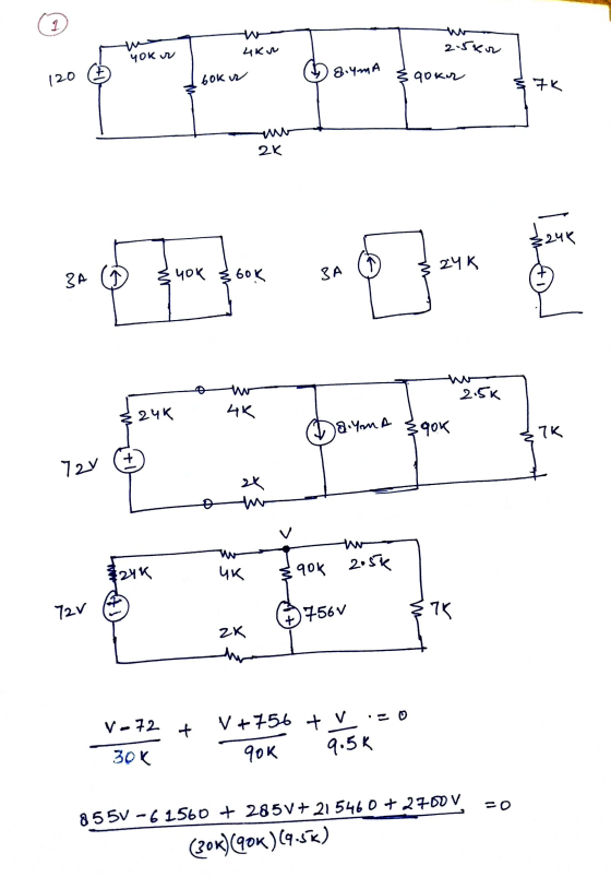
Consider the circuit shown in (Figure 1). Suppose that R = 6 kΩ. Find the current...
 Consider the circuit shown in (Figure 1). Suppose that R = 6
kΩ.
Find the current io in the circuit by making a succession of
appropriate source transformations.
Express your answer to three significant figures and include the
appropriate units.
Work back through the circuit to find the magnitude of the power
developed by the 120 V source.
Express your answer to three significant figures and include the
appropriate units.
40 kΩ Αν 4 kΩ 2.5 kΩ Αν +) 120...
Consider the circuit shown in (Figure 1). Suppose that R = 6
kΩ.
Find the current io in the circuit by making a succession of
appropriate source transformations.
Express your answer to three significant figures and include the
appropriate units.
Work back through the circuit to find the magnitude of the power
developed by the 120 V source.
Express your answer to three significant figures and include the
appropriate units.
40 kΩ Αν 4 kΩ 2.5 kΩ Αν +) 120...
PLEASE BOX ALL ANSWERS FOR A THUMBS UP Consider the circuit shown in (Figure 1). Suppose...
 PLEASE BOX ALL ANSWERS FOR A THUMBS UP
Consider the circuit shown in (Figure 1). Suppose that R = 7 kN. Find the current i, in the circuit by making a succession of appropriate source transformations. Express your answer to three significant figures and include the appropriate units. uA ? io = Value Units Submit Previous Answers Request Answer X Incorrect; Try Again; 5 attempts remaining Check your signs. Figure Part B 1 of 1 Work back through the circuit...
PLEASE BOX ALL ANSWERS FOR A THUMBS UP
Consider the circuit shown in (Figure 1). Suppose that R = 7 kN. Find the current i, in the circuit by making a succession of appropriate source transformations. Express your answer to three significant figures and include the appropriate units. uA ? io = Value Units Submit Previous Answers Request Answer X Incorrect; Try Again; 5 attempts remaining Check your signs. Figure Part B 1 of 1 Work back through the circuit...
Constants Part A Consider the circuit shown in (Figure 1). Suppose that 9 kΩ Find the...
 Constants Part A Consider the circuit shown in (Figure 1). Suppose that 9 kΩ Find the current i in the circuit by making a succession of appropriate source transformations Express your answer to three significant figures and include the appropriate units i,Value Units Submit Request Answer Figure 1 of 1 Part B Work back through the circuit to find the magnitude of the power developed by the 120 V source Express your answer to three significant figures and include the...
please box all answers Find the Norton equivalent with respect to the terminals a,b for the...
 please box all answers
Find the Norton equivalent with respect to the terminals a,b for the circuit seen in (Figure 1). Suppose that vg = 220 V and R = 5.0 k 2. Part A Find the equivalent current. Express your answer to three significant figures and include the appropriate units. μΑ in = Value Units Submit Request Answer Part B Figure 1 of 1 Find the equivalent resistance. Express your answer to three significant figures and include the appropriate...
please box all answers
Find the Norton equivalent with respect to the terminals a,b for the circuit seen in (Figure 1). Suppose that vg = 220 V and R = 5.0 k 2. Part A Find the equivalent current. Express your answer to three significant figures and include the appropriate units. μΑ in = Value Units Submit Request Answer Part B Figure 1 of 1 Find the equivalent resistance. Express your answer to three significant figures and include the appropriate...
Part D? The op amp in the circuit in (Figure 1) is ideal. Suppose R =...
 Part D?
The op amp in the circuit in (Figure 1) is ideal. Suppose R = 35 kΩ. Figure K 1 of 1 Σ 60 kΩ 30 ΚΩ 8 ΚΩ 15 V W X40 ΚΩ + 240 mV -15V Part A Calculate ia Express your answer to three significant figures and include the appropriate units. ia = 3.00x10⁻⁵ A Submit Previous Answers Correct Part B Calculate va Express your answer to three significant figures and include the appropriate units. Va...
Part D?
The op amp in the circuit in (Figure 1) is ideal. Suppose R = 35 kΩ. Figure K 1 of 1 Σ 60 kΩ 30 ΚΩ 8 ΚΩ 15 V W X40 ΚΩ + 240 mV -15V Part A Calculate ia Express your answer to three significant figures and include the appropriate units. ia = 3.00x10⁻⁵ A Submit Previous Answers Correct Part B Calculate va Express your answer to three significant figures and include the appropriate units. Va...
reviewIwona Consider the circuit in (Figure 1). Suppose that i = 1.6 A and y =...
 reviewIwona Consider the circuit in (Figure 1). Suppose that i = 1.6 A and y = 28 V Part A Use a series of source transformations to find in in the circuit. Express your answer to three significant figures and include the appropriate units. View Available Hint(s) μΑ ? 0.399 A Submit Previous Answers X Incorrect: Try Again: 4 attempts remaining Part B Complete previous part(s) Provide Feedback Next > Figure 1 of 1 > 612 02 5 Ω w...
please box all answers for a thumbs up Problem 4.66 Find the Norton equivalent with respect...
 please box all answers for a thumbs up
Problem 4.66 Find the Norton equivalent with respect to the terminals a,b for the circuit in (Figure 1) if v = 20 V, i = 7 A. Figure 1 of 1 212 w V 2692 b Part A Find the equivalent current. Express your answer to three significant figures and include the appropriate units. HÅ ? IN = Value Units Submit Request Answer Part B Find the equivalent resistance. Express your answer...
please box all answers for a thumbs up
Problem 4.66 Find the Norton equivalent with respect to the terminals a,b for the circuit in (Figure 1) if v = 20 V, i = 7 A. Figure 1 of 1 212 w V 2692 b Part A Find the equivalent current. Express your answer to three significant figures and include the appropriate units. HÅ ? IN = Value Units Submit Request Answer Part B Find the equivalent resistance. Express your answer...
Problem 4.32 Consider the circuit shown in (Figure 1). Use the mesh- current method to find...
 Problem 4.32 Consider the circuit shown in (Figure 1). Use the mesh- current method to find the branch currents ia - ze in the circuit. Take v1 = 32 V and ug = 2 V. Part A Find in Express your answer to three significant figures and include the appropriate units. HÅ ? Value Units Submit Previous Answers Request Answer X Incorrect; Try Again; 3 attempts remaining Part B Find is. Express your answer to three significant figures and include...
Please answer all parts Consider the circuit shown in (Figure 1). Suppose that Ve = 50070°V...
 Please answer all parts
Consider the circuit shown in (Figure 1). Suppose that Ve = 50070°V (rms). Express your answer to three significant figures and include the appropriate units. View Available Hint(s) IT HA ? 21 = Value Units Submit Part D Find the average power dissipated in the line when the capacitive reactance is connected across the load. Express your answer to three significant figures and include the appropriate units. THA th ? P- Value Units Submit Request Answer...
Please answer all parts
Consider the circuit shown in (Figure 1). Suppose that Ve = 50070°V (rms). Express your answer to three significant figures and include the appropriate units. View Available Hint(s) IT HA ? 21 = Value Units Submit Part D Find the average power dissipated in the line when the capacitive reactance is connected across the load. Express your answer to three significant figures and include the appropriate units. THA th ? P- Value Units Submit Request Answer...
Problem 4.7 Consider the circuit shown in (Figure 1). The source voltage v1 is 40 V....
 Problem 4.7 Consider the circuit shown in (Figure 1). The source voltage v1 is 40 V. Resistance R1, R2 and R3 are 5 ,120 and 15 , respectively. The source current I is 25 mA Part A Find the power developed by the current source I in the circuit. Express your answer to three significant figures and include the appropriate units. НА Value Units Рi 3 Request Answer Submit Part B Figure 1 of 1 Find the power developed by...
 Consider the circuit shown in (Figure 1). Suppose that R = 6
kΩ.
Find the current io in the circuit by making a succession of
appropriate source transformations.
Express your answer to three significant figures and include the
appropriate units.
Work back through the circuit to find the magnitude of the power
developed by the 120 V source.
Express your answer to three significant figures and include the
appropriate units.
40 kΩ Αν 4 kΩ 2.5 kΩ Αν +) 120...
Consider the circuit shown in (Figure 1). Suppose that R = 6
kΩ.
Find the current io in the circuit by making a succession of
appropriate source transformations.
Express your answer to three significant figures and include the
appropriate units.
Work back through the circuit to find the magnitude of the power
developed by the 120 V source.
Express your answer to three significant figures and include the
appropriate units.
40 kΩ Αν 4 kΩ 2.5 kΩ Αν +) 120...
 PLEASE BOX ALL ANSWERS FOR A THUMBS UP
Consider the circuit shown in (Figure 1). Suppose that R = 7 kN. Find the current i, in the circuit by making a succession of appropriate source transformations. Express your answer to three significant figures and include the appropriate units. uA ? io = Value Units Submit Previous Answers Request Answer X Incorrect; Try Again; 5 attempts remaining Check your signs. Figure Part B 1 of 1 Work back through the circuit...
PLEASE BOX ALL ANSWERS FOR A THUMBS UP
Consider the circuit shown in (Figure 1). Suppose that R = 7 kN. Find the current i, in the circuit by making a succession of appropriate source transformations. Express your answer to three significant figures and include the appropriate units. uA ? io = Value Units Submit Previous Answers Request Answer X Incorrect; Try Again; 5 attempts remaining Check your signs. Figure Part B 1 of 1 Work back through the circuit...
 Constants Part A Consider the circuit shown in (Figure 1). Suppose that 9 kΩ Find the current i in the circuit by making a succession of appropriate source transformations Express your answer to three significant figures and include the appropriate units i,Value Units Submit Request Answer Figure 1 of 1 Part B Work back through the circuit to find the magnitude of the power developed by the 120 V source Express your answer to three significant figures and include the...
 please box all answers
Find the Norton equivalent with respect to the terminals a,b for the circuit seen in (Figure 1). Suppose that vg = 220 V and R = 5.0 k 2. Part A Find the equivalent current. Express your answer to three significant figures and include the appropriate units. μΑ in = Value Units Submit Request Answer Part B Figure 1 of 1 Find the equivalent resistance. Express your answer to three significant figures and include the appropriate...
please box all answers
Find the Norton equivalent with respect to the terminals a,b for the circuit seen in (Figure 1). Suppose that vg = 220 V and R = 5.0 k 2. Part A Find the equivalent current. Express your answer to three significant figures and include the appropriate units. μΑ in = Value Units Submit Request Answer Part B Figure 1 of 1 Find the equivalent resistance. Express your answer to three significant figures and include the appropriate...
 Part D?
The op amp in the circuit in (Figure 1) is ideal. Suppose R = 35 kΩ. Figure K 1 of 1 Σ 60 kΩ 30 ΚΩ 8 ΚΩ 15 V W X40 ΚΩ + 240 mV -15V Part A Calculate ia Express your answer to three significant figures and include the appropriate units. ia = 3.00x10⁻⁵ A Submit Previous Answers Correct Part B Calculate va Express your answer to three significant figures and include the appropriate units. Va...
Part D?
The op amp in the circuit in (Figure 1) is ideal. Suppose R = 35 kΩ. Figure K 1 of 1 Σ 60 kΩ 30 ΚΩ 8 ΚΩ 15 V W X40 ΚΩ + 240 mV -15V Part A Calculate ia Express your answer to three significant figures and include the appropriate units. ia = 3.00x10⁻⁵ A Submit Previous Answers Correct Part B Calculate va Express your answer to three significant figures and include the appropriate units. Va...
 reviewIwona Consider the circuit in (Figure 1). Suppose that i = 1.6 A and y = 28 V Part A Use a series of source transformations to find in in the circuit. Express your answer to three significant figures and include the appropriate units. View Available Hint(s) μΑ ? 0.399 A Submit Previous Answers X Incorrect: Try Again: 4 attempts remaining Part B Complete previous part(s) Provide Feedback Next > Figure 1 of 1 > 612 02 5 Ω w...
 please box all answers for a thumbs up
Problem 4.66 Find the Norton equivalent with respect to the terminals a,b for the circuit in (Figure 1) if v = 20 V, i = 7 A. Figure 1 of 1 212 w V 2692 b Part A Find the equivalent current. Express your answer to three significant figures and include the appropriate units. HÅ ? IN = Value Units Submit Request Answer Part B Find the equivalent resistance. Express your answer...
please box all answers for a thumbs up
Problem 4.66 Find the Norton equivalent with respect to the terminals a,b for the circuit in (Figure 1) if v = 20 V, i = 7 A. Figure 1 of 1 212 w V 2692 b Part A Find the equivalent current. Express your answer to three significant figures and include the appropriate units. HÅ ? IN = Value Units Submit Request Answer Part B Find the equivalent resistance. Express your answer...
 Problem 4.32 Consider the circuit shown in (Figure 1). Use the mesh- current method to find the branch currents ia - ze in the circuit. Take v1 = 32 V and ug = 2 V. Part A Find in Express your answer to three significant figures and include the appropriate units. HÅ ? Value Units Submit Previous Answers Request Answer X Incorrect; Try Again; 3 attempts remaining Part B Find is. Express your answer to three significant figures and include...
 Please answer all parts
Consider the circuit shown in (Figure 1). Suppose that Ve = 50070°V (rms). Express your answer to three significant figures and include the appropriate units. View Available Hint(s) IT HA ? 21 = Value Units Submit Part D Find the average power dissipated in the line when the capacitive reactance is connected across the load. Express your answer to three significant figures and include the appropriate units. THA th ? P- Value Units Submit Request Answer...
Please answer all parts
Consider the circuit shown in (Figure 1). Suppose that Ve = 50070°V (rms). Express your answer to three significant figures and include the appropriate units. View Available Hint(s) IT HA ? 21 = Value Units Submit Part D Find the average power dissipated in the line when the capacitive reactance is connected across the load. Express your answer to three significant figures and include the appropriate units. THA th ? P- Value Units Submit Request Answer...
 Problem 4.7 Consider the circuit shown in (Figure 1). The source voltage v1 is 40 V. Resistance R1, R2 and R3 are 5 ,120 and 15 , respectively. The source current I is 25 mA Part A Find the power developed by the current source I in the circuit. Express your answer to three significant figures and include the appropriate units. НА Value Units Рi 3 Request Answer Submit Part B Figure 1 of 1 Find the power developed by...
Most questions answered within 3 hours.
-
A hair is placed at one edge between two flat glass plates 10.7
cm long. When...
asked 57 seconds ago -
The daily closing price of FPT stock over last year would
be:
A.Time series data
B.Cross...
asked 1 minute ago -
1. The government has now decided to implement a price ceiling
of $100 in this market....
asked 3 minutes ago -
An object with charge q = −4.00×10⁻⁹ C is placed in a region of
uniform electric...
asked 25 minutes ago -
A retired couple buys a new recreational vehicle (RV) for $ 50
comma 000.00 . They...
asked 23 minutes ago -
Question 1 (1 point)
What's measured in mass spectrometry?
Frequency
Atomic number
Mass
Molecular weight
Question...
asked 37 minutes ago -
Jupiter Satellite
Corporation earned $19.8 million for the fiscal year ending
yesterday. The firm also paid...
asked 43 minutes ago -
Your pizza restaurant uses the finest food ingredients to make
authentic brick-oven pizzas, and your mozarella...
asked 35 minutes ago -
How does social media affect and reflect on today’s culture?
asked 39 minutes ago -
Value-Stream Costing Objective
During the week of June 12, Harrison Manufacturing produced and
shipped 18,200 units...
asked 41 minutes ago -
The following chemical reaction occurs in a
basic solution.
Mg2+(aq) +
MnO2(aq) + OH−(aq) →
Mg(s)...
asked 53 minutes ago -
Visitor from Con Ed from a galaxy far away have placed a large
(black) ring of...
asked 58 minutes ago