
Homework Answers

Add Answer to:
For the following diagram, draw the shear and bending moment diagrams for the beam without formulating...
For the following diagram, draw the shear and bending moment diagrams for the beam. Include the shear force and bending moment equations.
 For the following diagram, draw the shear and bending moment diagrams for the beam. Include the shear force and bending moment equations.
Draw the shear force and bending-moment diagrams for the simply supported beam shown. Label each diagram...
 Draw the shear force and bending-moment diagrams for the simply
supported beam shown. Label each diagram with the corresponding
values
1. Draw the shear force and bending-moment diagrams for the simply supported beam shown. Label each diagram with the corresponding values. 3 Pe= 30 KN 4 m - m 3 m - C -40 kN - m
Draw the shear force and bending-moment diagrams for the simply
supported beam shown. Label each diagram with the corresponding
values
1. Draw the shear force and bending-moment diagrams for the simply supported beam shown. Label each diagram with the corresponding values. 3 Pe= 30 KN 4 m - m 3 m - C -40 kN - m
For the following beam: a) Derive the equations of shear-force and bending moment. b) Draw the...
 For the following beam:
a) Derive the equations of shear-force and bending moment.
b) Draw the diagrams of shear-force and bending moment
1.0 kip/ft A C 12 ft
For the following beam:
a) Derive the equations of shear-force and bending moment.
b) Draw the diagrams of shear-force and bending moment
1.0 kip/ft A C 12 ft
For the following diagram, draw the shear and bending-moment diagrams for the beam. The 50 lb/in...
 For the following diagram, draw the shear and bending-moment diagrams for the beam. The 50 lb/in load extends 12 inches from point A. 50 lb/in B С D E 450 lb 12 in. -10 in. 6 in. '4 in. -32 in.-
Q1. Draw the shear force and bending moment diagrams for the following cantilever beam
 Q1. Draw the shear force and bending moment diagrams for the following cantilever beam (10 marks). Q2. Draw the shear force and bending moment diagrams for the following simply supported beam (10 marks). Q3. Draw the shear force and bending moment diagrams for the following simply supported beam with cantilever extension (15 marks). Q4. Draw the shear force and bending moment diagrams for the following compound beam (15 marks).
Problem 2 - Draw the shear and bending moment diagrams for the beam shown below. Clearly...
 Problem 2 - Draw the shear and bending moment diagrams for the beam shown below. Clearly label th shear and moment values at all points. (25 points) 20 k 40 k-ft 5 ft 10 ft 10 ft
QUESTION 4 4. Bending Moment in a Beam Draw the shear and bending moment diagrams for...
 QUESTION 4 4. Bending Moment in a Beam Draw the shear and bending moment diagrams for the beam and loading shown. Then use the bending moment diagram to determine the bending moment in ſkip-ft] experienced by the beam at point D. 12 kips 12 kips 10 kips the С - 5 ft 5ft --- 2 ft 3 ft
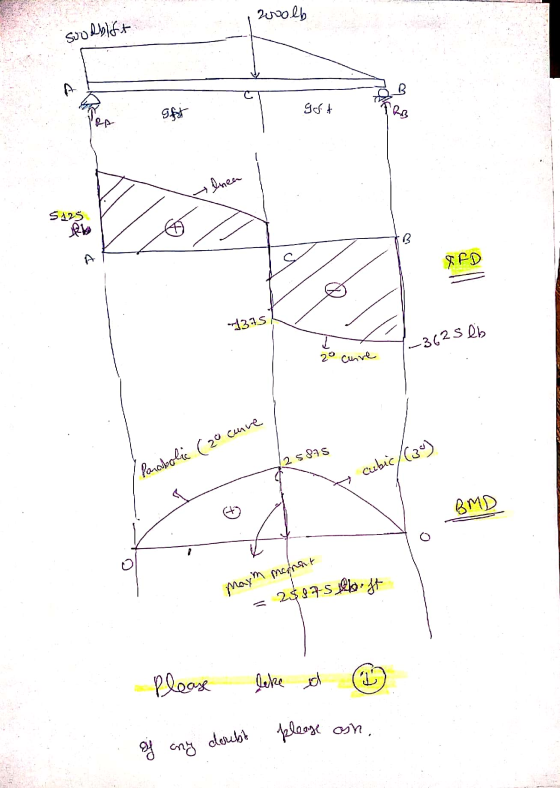
Problem 4. Sketch complete shear force and bending moment diagrams for the beam below. (30 Points)...
 Problem 4. Sketch complete shear force and bending moment diagrams for the beam below. (30 Points) 2000 lb V (lb) 0 M(ft lb) 0
explain how to draw the shear and bending moment diagram. 4. Draw the shear and bending...
 explain how to draw the shear and bending moment
diagram.
4. Draw the shear and bending moment diagrams for the beam and loading shown (include values on the shear and moment diagrams at points A, B, and ).
explain how to draw the shear and bending moment
diagram.
4. Draw the shear and bending moment diagrams for the beam and loading shown (include values on the shear and moment diagrams at points A, B, and ).
3. Draw the shear and bending-moment diagrams for the beam and loading shown, and determine the...
 3. Draw the shear and bending-moment diagrams for the beam and loading shown, and determine the maximum a bsolute value (a) of the shear, (b) of the bending moment. (40 Points) 300 lb 240 lb 360 lb CVDVE 4 in. 3 in. 4 in. 5 in.
 Draw the shear force and bending-moment diagrams for the simply
supported beam shown. Label each diagram with the corresponding
values
1. Draw the shear force and bending-moment diagrams for the simply supported beam shown. Label each diagram with the corresponding values. 3 Pe= 30 KN 4 m - m 3 m - C -40 kN - m
Draw the shear force and bending-moment diagrams for the simply
supported beam shown. Label each diagram with the corresponding
values
1. Draw the shear force and bending-moment diagrams for the simply supported beam shown. Label each diagram with the corresponding values. 3 Pe= 30 KN 4 m - m 3 m - C -40 kN - m
 For the following beam:
a) Derive the equations of shear-force and bending moment.
b) Draw the diagrams of shear-force and bending moment
1.0 kip/ft A C 12 ft
For the following beam:
a) Derive the equations of shear-force and bending moment.
b) Draw the diagrams of shear-force and bending moment
1.0 kip/ft A C 12 ft
 For the following diagram, draw the shear and bending-moment diagrams for the beam. The 50 lb/in load extends 12 inches from point A. 50 lb/in B С D E 450 lb 12 in. -10 in. 6 in. '4 in. -32 in.-
 Problem 2 - Draw the shear and bending moment diagrams for the beam shown below. Clearly label th shear and moment values at all points. (25 points) 20 k 40 k-ft 5 ft 10 ft 10 ft
 QUESTION 4 4. Bending Moment in a Beam Draw the shear and bending moment diagrams for the beam and loading shown. Then use the bending moment diagram to determine the bending moment in ſkip-ft] experienced by the beam at point D. 12 kips 12 kips 10 kips the С - 5 ft 5ft --- 2 ft 3 ft
 Problem 4. Sketch complete shear force and bending moment diagrams for the beam below. (30 Points) 2000 lb V (lb) 0 M(ft lb) 0
 explain how to draw the shear and bending moment
diagram.
4. Draw the shear and bending moment diagrams for the beam and loading shown (include values on the shear and moment diagrams at points A, B, and ).
explain how to draw the shear and bending moment
diagram.
4. Draw the shear and bending moment diagrams for the beam and loading shown (include values on the shear and moment diagrams at points A, B, and ).
 3. Draw the shear and bending-moment diagrams for the beam and loading shown, and determine the maximum a bsolute value (a) of the shear, (b) of the bending moment. (40 Points) 300 lb 240 lb 360 lb CVDVE 4 in. 3 in. 4 in. 5 in.
Most questions answered within 3 hours.
-
An MNE is this kind of industry when competition in one country
is essentially independent of...
asked 21 minutes ago -
. For this set of questions, determine what
proportion of a normal distribution is located betweeneach...
asked 56 minutes ago -
A college student is employed as a door-to-door newspaper
salesman. Historical data suggests that the student...
asked 1 hour ago -
MATLAB HW 11 problem using Switch Case and Input commands
Write a script file that calculates...
asked 1 hour ago -
Considering gravitational time dilation, calculate the time that
passes in Earth’s surface while 1 hour passes...
asked 2 hours ago -
Minitab Problem: Take the Lake Hume June rainfall data and find
use the processes outlined in...
asked 3 hours ago -
X Company is trying to decide whether to continue using old
equipment to make Product A...
asked 3 hours ago -
IN PYTHON ONLY !! Program 2: Re-work
program #5 (WeeklyHours) from the previous assignment such that...
asked 3 hours ago -
The average length of time between arrivals at a turnpike
toll-booth is 26 seconds. What is...
asked 5 hours ago -
(a) A piston at 6.1 atm contains a gas that occupies a volume of
3.5 L....
asked 6 hours ago -
Please answer true or false. Words
cannot be changed or added in to make it true...
asked 6 hours ago -
An empty test tube weighs 15.923 grams. Then,
MgCl2•6H2O is added into the test tube. After...
asked 6 hours ago