
Homework Answers
Please find the attachment


Add Answer to:
FEA
( finite element analysis )
c) Describe the boundary conditions needed to impose a symmetry...
FEA FEA question c) Describe the boundary conditions needed to impose a symmetry plane when using...
 FEA
FEA question
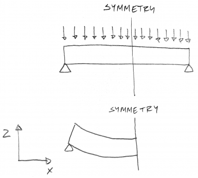
c) Describe the boundary conditions needed to impose a symmetry plane when using shell elements. We were unable to transcribe this image
FEA
FEA question
c) Describe the boundary conditions needed to impose a symmetry plane when using shell elements. We were unable to transcribe this image
FEA c) Describe the boundary conditions needed to impose a symmetry plane when using shell elements.
 FEA
c) Describe the boundary conditions needed to impose a symmetry plane when using shell elements.
FEA
c) Describe the boundary conditions needed to impose a symmetry plane when using shell elements.
FEA ( finite element analysis ) b) Describe an example of a harmonic response finite element...
 FEA ( finite element analysis )
b) Describe an example of a harmonic response finite element analysis c) Describe the difference between solid elements and shell elements. DO
FEA ( finite element analysis )
b) Describe an example of a harmonic response finite element analysis c) Describe the difference between solid elements and shell elements. DO
fea b) List the four material properties needed to perform a FE analysis using a bilinear...
 fea
b) List the four material properties needed to perform a FE analysis using a bilinear material. c) Describe the boundary conditions needed to impose a symmetry plane when using shell elements.
fea
b) List the four material properties needed to perform a FE analysis using a bilinear material. c) Describe the boundary conditions needed to impose a symmetry plane when using shell elements.
FEA ( finite element analysis ) c) In terms of performing a finite element analysis, describe...
 FEA
( finite element analysis )
c) In terms of performing a finite element analysis, describe the phrase "stress miffening, Inverse of buckling Increase in transverse stiffness wol increase of axial force d) Describe geometric nonlinearities and when they should be used.
FEA
( finite element analysis )
c) In terms of performing a finite element analysis, describe the phrase "stress miffening, Inverse of buckling Increase in transverse stiffness wol increase of axial force d) Describe geometric nonlinearities and when they should be used.
FEA ( finite element analysis ) d) Describe the difference between geometric nonlinearities and material nonlinearities....
 FEA ( finite element analysis )
d) Describe the difference between geometric nonlinearities and material nonlinearities. besede large do lacement Targe decoration Grobnion) Straw & plastic دل به جریان when there is inelastic bohano e) Describe how to include the self-weight of a structure when performing a finite element analysis. need
FEA ( finite element analysis )
d) Describe the difference between geometric nonlinearities and material nonlinearities. besede large do lacement Targe decoration Grobnion) Straw & plastic دل به جریان when there is inelastic bohano e) Describe how to include the self-weight of a structure when performing a finite element analysis. need
FEA ( finite element analysis ) coccurote For displacement-based elements, is convergence from above" or "from...
 FEA
( finite element analysis )
coccurote For displacement-based elements, is convergence from above" or "from below?" - It is more
FEA
( finite element analysis )
coccurote For displacement-based elements, is convergence from above" or "from below?" - It is more
b) List the four material properties needed to perform analysis using a bilinear material c) Describe...
 b) List the four material properties needed to perform analysis using a bilinear material c) Describe the boundary conditions needed to impose a symmetry plane when using shell elements. d) Provide an example of when you would use the explicit dynamics analysis system. Describe adaptive meshing.
Problem 1: Finite element analysis project (part 2) Consider the beam that was modeled using Soli...
 Problem 1: Finite element analysis project (part 2) Consider the beam that was modeled using SolidWorks in Part 1 5mm- 80mm 100mm 10m Let the beam be made out of A36 structural steel. Determine and plot: (1a) e deflection of the beam h(x) Note: do not forget to convert pressure to force/length (1b) the normal stress in the beam ơxx(x, y, z) For the plots, let y - 0,z - 48mm) No partial answer is provided here you should check...
 FEA
FEA question
c) Describe the boundary conditions needed to impose a symmetry plane when using shell elements. We were unable to transcribe this image
FEA
FEA question
c) Describe the boundary conditions needed to impose a symmetry plane when using shell elements. We were unable to transcribe this image
 FEA
c) Describe the boundary conditions needed to impose a symmetry plane when using shell elements.
FEA
c) Describe the boundary conditions needed to impose a symmetry plane when using shell elements.
 FEA ( finite element analysis )
b) Describe an example of a harmonic response finite element analysis c) Describe the difference between solid elements and shell elements. DO
FEA ( finite element analysis )
b) Describe an example of a harmonic response finite element analysis c) Describe the difference between solid elements and shell elements. DO
 fea
b) List the four material properties needed to perform a FE analysis using a bilinear material. c) Describe the boundary conditions needed to impose a symmetry plane when using shell elements.
fea
b) List the four material properties needed to perform a FE analysis using a bilinear material. c) Describe the boundary conditions needed to impose a symmetry plane when using shell elements.
 FEA
( finite element analysis )
c) In terms of performing a finite element analysis, describe the phrase "stress miffening, Inverse of buckling Increase in transverse stiffness wol increase of axial force d) Describe geometric nonlinearities and when they should be used.
FEA
( finite element analysis )
c) In terms of performing a finite element analysis, describe the phrase "stress miffening, Inverse of buckling Increase in transverse stiffness wol increase of axial force d) Describe geometric nonlinearities and when they should be used.
 FEA ( finite element analysis )
d) Describe the difference between geometric nonlinearities and material nonlinearities. besede large do lacement Targe decoration Grobnion) Straw & plastic دل به جریان when there is inelastic bohano e) Describe how to include the self-weight of a structure when performing a finite element analysis. need
FEA ( finite element analysis )
d) Describe the difference between geometric nonlinearities and material nonlinearities. besede large do lacement Targe decoration Grobnion) Straw & plastic دل به جریان when there is inelastic bohano e) Describe how to include the self-weight of a structure when performing a finite element analysis. need
 FEA
( finite element analysis )
coccurote For displacement-based elements, is convergence from above" or "from below?" - It is more
FEA
( finite element analysis )
coccurote For displacement-based elements, is convergence from above" or "from below?" - It is more
 b) List the four material properties needed to perform analysis using a bilinear material c) Describe the boundary conditions needed to impose a symmetry plane when using shell elements. d) Provide an example of when you would use the explicit dynamics analysis system. Describe adaptive meshing.
 Problem 1: Finite element analysis project (part 2) Consider the beam that was modeled using SolidWorks in Part 1 5mm- 80mm 100mm 10m Let the beam be made out of A36 structural steel. Determine and plot: (1a) e deflection of the beam h(x) Note: do not forget to convert pressure to force/length (1b) the normal stress in the beam ơxx(x, y, z) For the plots, let y - 0,z - 48mm) No partial answer is provided here you should check...
Most questions answered within 3 hours.
-
Montecino Corporation uses two different types of labor to
manufacture its product. The types of labor,...
asked 17 minutes ago -
4. What are the two possible products of the
intramolecular hemiacetal formation of linear glucose?
5. ...
asked 38 minutes ago -
The opportunity cost of attending university is likely to
include all except which of the following?...
asked 41 minutes ago -
Consider the following regular
expression: (a*bc+d*e)*
Transform this regular expression to an NFA, from
there to...
asked 37 minutes ago -
1. The Janjua Company had the following account balances at
1/1/16: Common Stock $50,000 Treasury Stock...
asked 38 minutes ago -
A solution with maximum solute that can dissolve and remain
stable is
saturated
unsaturated
miscible
supersaturated
asked 43 minutes ago -
Describe how you would make 100ml of a 10mmol glucose
standard
asked 43 minutes ago -
Zahn Corp.'s comparative balance sheet at December 31, 20x5 and
20x4, reported accumulated depreciation balances of...
asked 44 minutes ago -
How many milliliters of 5.6 M NaOH are needed to neutralize 3.9
mL of a 6.6...
asked 55 minutes ago -
Will dislike
if you don't code efficiently, you must have knowledge of
next.js,vue.js,immutable.js,react,js.
Develop an api...
asked 1 hour ago -
When financial statements are converted to percentages, they are
referred to as:
A. Percent of change...
asked 1 hour ago -
16) Which of the following is not a way to reduce the
government's budget
deficit
A)...
asked 1 hour ago