
Homework Answers
(1) Single Slit Diffraction
In the single-slit diffraction experiment, we can observe the bending phenomenon of light or diffraction that causes light from a coherent source interfere with itself and produce a distinctive pattern on the screen called the diffraction pattern. Diffraction is evident when the sources are small enough that they are relatively the size of the wavelength of light
Single Slit Diffraction Formula
We shall assume the slit width a << D. x`D is the separation between slit and source.
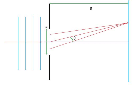
The angular position of any point on the screen by Θ measured from the slit centre which divides the slit by a/2 lengths. To describe the pattern, the condition for dark fringes. Also, divide the slit into zones of equal widths a/2. considering a pair of rays that emanate from distances a/2 from each other as shown below.
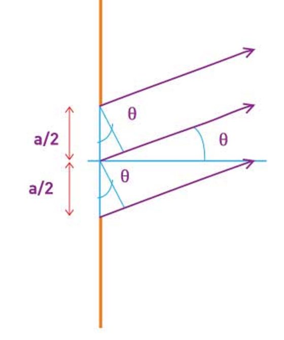
ΔL=(a/2)sinΘ
Remember that this is a calculation valid only if D is very large.
considering any number of ray pairings that start from a distance a/2 from one another such as the bottom two rays in the diagram. Any arbitrary pair of rays at a distance a/2 can be considered.
For a dark fringe, the path difference must cause destructive interference; the path difference must be out of phase by λ/2. (λ is the wavelength)
For the first fringe,
ΔL = λ/2 = (a/2)sinΘ
λ = a sin θ
For a ray emanating from any point in the slit, there exists another ray at a distance a2 that can cause destructive interference.
Thus, at θ = sin−1(λa), there is destructive interference as any ray emanating from a point has a counterpart that causes destructive interference. Hence, a dark fringe is obtained.
For the next fringe, we can divide the slit into 4 equal parts of a/4 and apply the same logic. Thus, for the second minima:
λ2=(a/4)sinΘ
2λ=asinΘ
Similarly, for the nth fringe, we can divide the slit into 2n parts and use this condition as
The Central Maximum
The maxima lie between the minima and the width of the central maximum is simply the distance between the 1st order minima from the centre of the screen on both sides of the centre.
The position of the minima given by y (measured from the centre of the screen) is:
tanθ≈θ≈y/D
For small ϑ,
sin θ≈θ
⇒ λ = a sin θ≈aθ
⇒ θ = y/D = λa
⇒ y = λDa
The width of the central maximum is simply twice this value
⇒ Width of central maximum = 2λDa
⇒ Angular width of central maximum = 2θ = 2λa
Fraunhofer diffraction is the type of diffraction that occurs in the limit of small Fresnel number . In Fraunhofer diffraction, the diffraction pattern is independent of the distance to the screen, depending only on the angles to the screen from the aperture.
A diffraction grating is an optical element that divides(disperses) light composed of lots of different wavelengths(e.g., white light) into light components by wavelength. The simplest type of grating is one with a large number of evenly spaced parallel slits. In optics, a diffraction grating is an optical component with a periodic structure that splits and diffracts light into several beams travelling in different directions.
use of diffraction grating in cd tracking
A recording on a CD is in the form of microscopic pits of different lengths that carry the information. These pits are placed in rows of the same width and equal distance, which form a diffraction grating on the mirror surface of the CD.
(2) Reflecting Telescope:
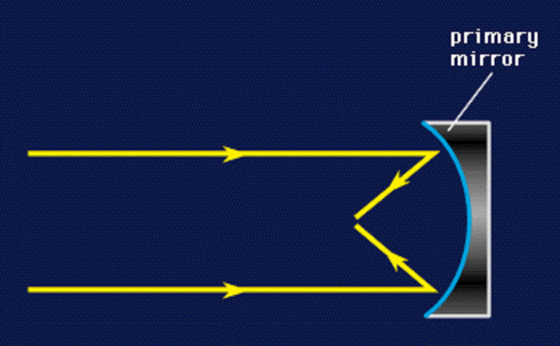
Reflectors are used not only to examine the visible region of the electromagnetic spectrum but also to explore both the shorter- and longer-wavelength regions adjacent to it (i.e., the ultraviolet and the infrared). The name of this type of instrument is derived from the fact that the primary mirror reflects the light back to a focus instead of refracting it. The primary mirror usually has a concave spherical or parabolic shape, and, as it reflects the light, it inverts the image at the focal plane. The figure below illustrates the principle of a concave reflecting mirror.
The primary mirror is located at the lower end of the telescope tube in a reflector and has its front surface coated with an extremely thin film of metal, such as aluminum. The back of the mirror is usually made of glass, although other materials have been used from time to time. Pyrex (trademark) was the principal glass of choice for many of the older large telescopes, but new technology has led to the development and widespread use of a number of glasses with very low coefficients of expansion. A low coefficient of expansion means that the shape of the mirror will not change significantly as the temperature of the telescope changes during the night. Since the back of the mirror serves only to provide the desired form and physical support, it does not have to meet the high optical quality standards required for a lens.
Reflecting telescopes have a number of other advantages over refractors. They are not subject to chromatic aberration because reflected light does not disperse according to wavelength. Also, the telescope tube of a reflector is shorter than that of a refractor of the same diameter, which reduces the cost of the tube. Consequently, the dome for housing a reflector is smaller and more economical to construct. So far only the primary mirror for the reflector has been discussed. In the figure, one might wonder about the location of the eyepiece. The primary mirror reflects the light of the celestial object to the prime focus near the upper end of the tube. Obviously, if an observer put his eye there to observe with a modest-sized reflector, he would block out the light from the primary mirror with his head. Isaac Newton placed a small plane mirror at an angle of 45 inside the prime focus and thereby brought the focus to the side of the telescope tube. The amount of light lost by this procedure is very small when compared to the total light-gathering power of the primary mirror. The Newtonian reflector is popular among amateur telescope makers.
A contemporary of Newton, N. Cassegrain of France, invented another type of reflector. Called the Cassegrainian telescope, this instrument employs a small convex mirror to reflect the light back through a small hole in the primary mirror to a focus located behind the primary. Figure 5 illustrates a typical Cassegrain reflector. Some large telescopes of this kind do not have a hole in the primary mirror but use a small plane mirror in front of the primary to reflect the light outside the main tube and provide another place for observation. The Cassegrain design usually permits short tubes relative to their mirror diameter.
 Most
large reflecting telescopes that are currently in use have a cage
at their prime focus that permits the observer to sit inside the
telescope tube while operating the instrument. The five-meter
reflector at Palomar Observatory, near San Diego, Calif., is so
equipped. Reflectors, like refractors, usually have small guide
telescopes mounted parallel to their main optical axis to
facilitate locating the desired object. These guide telescopes have
low magnification and a wide field of view, the latter being a
desirable attribute for finding stars or other remote cosmic
objects.
Most
large reflecting telescopes that are currently in use have a cage
at their prime focus that permits the observer to sit inside the
telescope tube while operating the instrument. The five-meter
reflector at Palomar Observatory, near San Diego, Calif., is so
equipped. Reflectors, like refractors, usually have small guide
telescopes mounted parallel to their main optical axis to
facilitate locating the desired object. These guide telescopes have
low magnification and a wide field of view, the latter being a
desirable attribute for finding stars or other remote cosmic
objects.
- For a circular aperture, lens, or mirror, the Rayleigh criterion states that two images are just resolvable when the center of the diffraction pattern of one is directly over the first minimum of the diffraction pattern of the other.
- This occurs for two point objects separated by the angle
 , where
  is the wavelength of
light (or other electromagnetic radiation) and
is the wavelength of
light (or other electromagnetic radiation) and  is the diameter of
the aperture, lens, mirror, etc. This equation also gives the
angular spreading of a source of light having a diameter .
is the diameter of
the aperture, lens, mirror, etc. This equation also gives the
angular spreading of a source of light having a diameter .
Add Answer to:
1. Explain single slit diffraction? What is Fraunhoffer diffraction? Describe diffraction grating and its use in...
Calculate the single slit width (a) for a destructive interference that occurs in case of single...
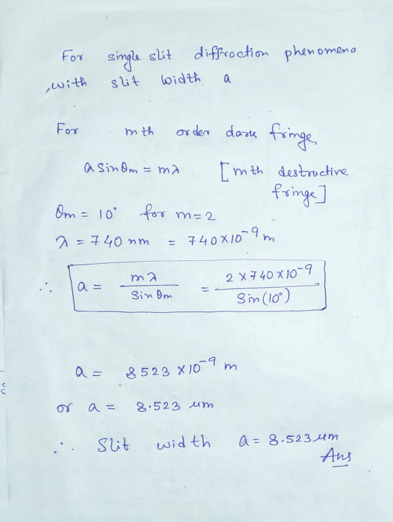
 Calculate the single slit width (a) for a destructive interference that occurs in case of single slit diffraction with dark = 10°, m= +2, and 2 = 740 nm?
please answer a,b, and c will rate! a) Calculate the single slit width (a) for a...
please answer a,b, and c will rate! a) Calculate the single slit width (a) for a destructive interference that occurs in case of single slit diffraction with θdark = 100, m = +2, and λ = 740 nm? b) What is the cut off wavelength (λc) for a photoelectric materials of work function 1.3 eV? c) What should be the energy of an atomic orbit if n=4? thank you!
1. Describe the pattern for the single-slit diffraction. How does it change when the slit width...
1. Describe the pattern for the single-slit diffraction. How does it change when the slit width changes? How does it change when the wavelength changes? 2. Describe the pattern for the double-slit interference. 3. Describe the pattern for the four-slit interference. 4. Compare the patterns of the single-slit diffraction to the double-slit interference.
1. A single slit forms a diffraction pattern, with the second minimum at an angle of...
1. A single slit forms a diffraction pattern, with the second minimum at an angle of 40.0° from central maximum, when monochromatic light of wavelength 630 nm is used. What is the width of the single slit? 2. Consider a two-slit experiment in which the slit separation is 3.0 × 10⁻⁵ m and the interference pattern is observed on a screen that is 2.00 m away from the slits. The wavelength of light passing through the slits is 420 nm....
1) In single slit diffraction, how does the position of the 1st dark fringe vary with...
1) In single slit diffraction, how does the position of the 1st dark fringe vary with the slit width and screen slit separation? 2) In double slit interference, how do the positions of the bright fringes vary with the slit separation and screen distance?
) In the figure, a slit 0.30 mm wide is illuminated by light of wavelength 426 nm. A diffraction attern is seen on a screen 2.8 m from the slit. What is the linear distance on the screen betw...
 ) In the figure, a slit 0.30 mm wide is illuminated by light of wavelength 426 nm. A diffraction attern is seen on a screen 2.8 m from the slit. What is the linear distance on the screen between e first diffraction minima on either side of the central diffraction maximum? Answer: 8.0 mm 30) A thin beam of laser light of wavelength 514 nm passes through a diffraction grating having 3952 lines/cm. The resulting pattern is viewed on a...
I think this is a single slit diffraction, but I need help Light from an argon...
 I think this is a single slit diffraction, but I need
help
Light from an argon laser produces light at lambda = 515 nm. This light is used to form a diffraction pattern through a diffraction grating with slit spacing of 2 mu m. The interference pattern is observed on a screen 0.7 m behind the slits. Draw a picture to show both a & b: a. What's the maximum number of bright fringes that could be observed. b. What...
I think this is a single slit diffraction, but I need
help
Light from an argon laser produces light at lambda = 515 nm. This light is used to form a diffraction pattern through a diffraction grating with slit spacing of 2 mu m. The interference pattern is observed on a screen 0.7 m behind the slits. Draw a picture to show both a & b: a. What's the maximum number of bright fringes that could be observed. b. What...
1) In Young's double-slit experiment what is the condition for a bright fringe? Give your answer...
1) In Young's double-slit experiment what is the condition for a bright fringe? Give your answer both in words and in equation form. 2) is bright fringe caused by constructive or destructive interference between the waves from two slits? 3) what is the condition for destructive interference in a single slit diffraction pattern? Give your answer both in words and in equation form.
488 nm light passes through a single slit. The first (m = 1) diffraction minimum occurs...
488 nm light passes through a single slit. The first (m = 1) diffraction minimum occurs at an angle of .559°. What is the width of the slit? Answer must be ____ x 10^-5 m.
4) Interference and Diffraction Phenomena (10 points) (a) In a single slit diffraction experiment with a...
 4) Interference and Diffraction Phenomena (10 points) (a) In a single slit diffraction experiment with a screen far away from the slit, with waves of wavelength 1, there will be no intensity minima if the slit becomes too small compared to the wavelength. What is the minimum slit width (in terms of ) for which no intensity minimum occurs? (Note: if there is no minimum, the screen looks essentially fully illuminated. Think what condition that puts on the angle of...
 Calculate the single slit width (a) for a destructive interference that occurs in case of single slit diffraction with dark = 10°, m= +2, and 2 = 740 nm?
 ) In the figure, a slit 0.30 mm wide is illuminated by light of wavelength 426 nm. A diffraction attern is seen on a screen 2.8 m from the slit. What is the linear distance on the screen between e first diffraction minima on either side of the central diffraction maximum? Answer: 8.0 mm 30) A thin beam of laser light of wavelength 514 nm passes through a diffraction grating having 3952 lines/cm. The resulting pattern is viewed on a...
 I think this is a single slit diffraction, but I need
help
Light from an argon laser produces light at lambda = 515 nm. This light is used to form a diffraction pattern through a diffraction grating with slit spacing of 2 mu m. The interference pattern is observed on a screen 0.7 m behind the slits. Draw a picture to show both a & b: a. What's the maximum number of bright fringes that could be observed. b. What...
I think this is a single slit diffraction, but I need
help
Light from an argon laser produces light at lambda = 515 nm. This light is used to form a diffraction pattern through a diffraction grating with slit spacing of 2 mu m. The interference pattern is observed on a screen 0.7 m behind the slits. Draw a picture to show both a & b: a. What's the maximum number of bright fringes that could be observed. b. What...
 4) Interference and Diffraction Phenomena (10 points) (a) In a single slit diffraction experiment with a screen far away from the slit, with waves of wavelength 1, there will be no intensity minima if the slit becomes too small compared to the wavelength. What is the minimum slit width (in terms of ) for which no intensity minimum occurs? (Note: if there is no minimum, the screen looks essentially fully illuminated. Think what condition that puts on the angle of...
Most questions answered within 3 hours.
-
1. Are all good samples random?
2. Magazines often report surveys giving statistics such as “63%...
asked 19 minutes ago -
Under all the various types of market structures, firms
must eventually earn some economic profits for...
asked 6 minutes ago -
Consider the following fitness regime for a single locus trait
with two co-dominant alleles: w11 =...
asked 10 minutes ago -
A large cable company reports the following.
80% of its customers subscribe to its cable TV...
asked 26 minutes ago -
Please answer the question in brief.
Discuss the role of ERP in organizations. Are ERP tools...
asked 12 minutes ago -
Discuss the pros and cons of collaborative software such
as SameTime. Does it increase productivity? What...
asked 24 minutes ago -
Buying your in-laws a gift because it’s expected is
due to the ____________ motive of gift-giving....
asked 27 minutes ago -
Calculate the expected value, the variance, and the standard
deviation of the given random variable X....
asked 1 hour ago -
A hospital performs 100 surgeries per week. The probability that
complications after surgery occur is 10%....
asked 1 hour ago -
1 point) Given the significance level α=0.01 find the following:
(a) left-tailed z value z= (b)...
asked 1 hour ago -
Assuming you are the head of the software development unit at
Cyber.Soft, explain and justify why...
asked 34 minutes ago -
Magnesium and nitrogen react in a combination reaction to
produce magnesium nitride. 3 Mg + N2...
asked 42 minutes ago