
Homework Answers
Given Information :


Solution :
(a) Critical Dimension :
Ans :
Let the reactions at the supports be : 
Using the static equilibrium equations :


Taking moment about point A :


Therefore :
Finding the position and the value of Maximum Bending moment along the beam :
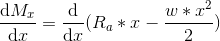
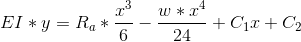
Writing the Moment equation of an arbitrary section taken at a distance of x from the hinged support at A:

In order to find the position of maximum bending moment, differentiate the above equation with respect to x and equate it to zero.
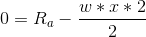


Therefore at a distance of
from the hinged support, maximum bending moment occurs.
Substitute the value to find the maximum bending moment :


From the equation of pure bending
where
Bending moment
Area Moment of
Inertia about Neutral Axis
Bending
stress
Distance between the neutral axis and the fiber at which bending
stress is being calculated
Young's Modulus of elasticity
Radius of curvature of elastic curve

Substitute the values for maximum bending stress :


Therefore considering bending stress, the critical
dimension is :
Finding the position and the value of Maximum Shear force,
along the length of the beam:
Writing the Shear force equation for the given loading, taking an arbitrary section at a distance x from the hinged support at point A:

As it can be seen that the shear force equation is linear, the
maximum shear force is at ; 

Finding the critical dimension based on Maximum shear stress :
Since the given section is a rectangle :


Substitute the values :


Therefore considering shear loads, the critical
dimension is :
(b) Maximum deflection :
Ans :
Considering the critical dimension :
Calculating the Area moment of Inertia :


Writing the Deflection equation :


Integrating the equation :

Integrating the equation :
Finding the constants of integation using the boundary conditions :


The Deflection equation is :

The Maximum Deflection is :
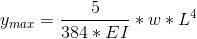
Substitute the values :


Therefore the maximum deflection is
: .
Add Answer to:
You are part of a team that is designing a structural component. The applied pressure loading...
You have been tasked with designing a beam to support a lifting crane. The applied load...
 You have been tasked with designing a beam to support a lifting crane. The applied load is offset from the center of the carriage used to mount the crane to the overhead beam. Therefore the loads applied to the two axels, P1 and P2, differ. You should use your student number to determine the magnitude of the applied loads. The position of the crane can vary (dependent on the variable, x, shown below) Example of a lifting crane Structural idealisation...
QuestioN1 You are workingon a team that is building a lightweight, remote-controlled aircraft wit...
 QuestioN1 You are workingon a team that is building a lightweight, remote-controlled aircraft with the goal of lifting as much payload as possible. Your team has selected a design that will use a rectangular wing with a constant cross-section in the form of a high-lift airfoil. You are responsible for the initial sizing of the load carrying spar that runs the entire span of the wing. In flight, the spar acts much like a loaded cantilevered beam, as shown in...
 You have been tasked with designing a beam to support a lifting crane. The applied load is offset from the center of the carriage used to mount the crane to the overhead beam. Therefore the loads applied to the two axels, P1 and P2, differ. You should use your student number to determine the magnitude of the applied loads. The position of the crane can vary (dependent on the variable, x, shown below) Example of a lifting crane Structural idealisation...
 QuestioN1 You are workingon a team that is building a lightweight, remote-controlled aircraft with the goal of lifting as much payload as possible. Your team has selected a design that will use a rectangular wing with a constant cross-section in the form of a high-lift airfoil. You are responsible for the initial sizing of the load carrying spar that runs the entire span of the wing. In flight, the spar acts much like a loaded cantilevered beam, as shown in...
Most questions answered within 3 hours.
-
In which direction the Reaction goes? Show detailed process.
SeO3 + 2ClO2. + 2H3O <---> Se...
asked 11 minutes ago -
Unexposed silver halides are removed from photographic film when
they react with sodium thiosulfate
(Na2S2O3, called...
asked 11 minutes ago -
A 0.3054 gram sample of the mineral chalcopyrite (CuFeS2)
yielded 0.6525 gram BaSO4 precipitate. What is...
asked 11 minutes ago -
An short-seller in Tesla is worried the latest management
earnings forecast is too aggressive and the...
asked 58 minutes ago -
Question 3 (1 point)
Fill in the blank. Speed Car Rental company found that the tire...
asked 57 minutes ago -
1. A copper wire is 26.61 cm long and weighs 1.265 g. The
density of copper...
asked 35 minutes ago -
Remember that a concept sketch consists of a sketch (or
series of sketches), labels, and complete...
asked 37 minutes ago -
on a newly discovered planet, the period of a pendulum with a
length of 2 m...
asked 40 minutes ago -
Why [M(CN)6] is not organometallic even it has metal
to carbon bond too
asked 46 minutes ago -
mstar electric has a bond issue outstanding that has a 20 year
life, a $1,000 par...
asked 53 minutes ago -
This is a Business Writing Question:
Common Types of Faulty Sentence Logic:
A. Mixed constructions
B....
asked 54 minutes ago -
Skinner asserts that science, and the common view of science, has
been tarnished. Explain his evidence...
asked 57 minutes ago