
Homework Answers

Add Answer to:
Problem Statement 1 The pump in the system shown below is used to transport water from...
4.45 A two-tank pump/pipe system has a head requirement of 23.4 ft at a flow rate of 100 gpm. The...
 4.45 A two-tank pump/pipe system has a head requirement of 23.4 ft at a flow rate of 100 gpm. The elevation difference between the fluid surfaces in the tanks is 10 ft. The pump is a Bell & Gossett Series e-80 Model 2.5x2.5x9C operating at 1170 rpm with a 7.5-inch impeller. a. Develop an cquation for the system curve. b. Use a computer program to develop an equation for the 7.5-inch impeller using data read from the pump performance curve...
Problem #3: The performance data for a centrifugal water pump are shown in Table P14-31 for water at 20°c (Lpm = liters...
 Problem #3: The performance data for a centrifugal water pump are shown in Table P14-31 for water at 20°c (Lpm = liters per minute). (a) For each row of data, calculate the pump efficiency (percent). Show all units. (b) Estimate the volume flow rate (Lpm) and net head (m) at the BEP of the pump.(c) Plot the pump's performance data: H, bhp, and pump efficiency as function of volume flow rate. H bhp Lpm) (m) (W) 0.0 47.5 133 6.0...
08 % Problem 4 (25 points) A 38-in pump is installed for the system below. The...
 08 % Problem 4 (25 points) A 38-in pump is installed for the system below. The pipe (100-cm diameter) has a friction factor of 0.012 and a total length of 20 km. Given that Ke = 0.5 (pipe entrance) and Ke = 1.0 (pipe exit). For water at 80 degrees Fahrenheit, estimate the flow rate (in gpm), the power required (in horsepower, HP), and the net positive suction head required (in ft) to avoid cavitation for the system when the...
Project-Design Problem: A family of water pumps produced by a given pump manufacturer have performance and...
 Project-Design Problem: A family of water pumps produced by a given pump manufacturer have performance and efficiency curves that can be characterized by the following dimensionless equations: Pump head 6 = 6.04-1616 where and 5 nD Pump efficiency n = 705-91,5006 where n = (power to water) / (elect power input) In the above equations, is the dimensionless pump head and is the dimensionless volumetric flow rate. h, is the pump head, n is the pump shaft/impeller rotation rate, and...
3. A pump is to be used to pump water from the lower re servoir at an elevation of 10 ft The pump has a characteristic curve ft up to a reservoir shown in the graph below. What will be the volum...
 3. A pump is to be used to pump water from the lower re servoir at an elevation of 10 ft The pump has a characteristic curve ft up to a reservoir shown in the graph below. What will be the volumetric flow rate of the water in this system? Elevation- 35 ft L- 50 t D-10 in -0.020 L-950 ft rid- Elevation 20A D-10 i -0.020 Elevation-15ft 80 60 40 Pump curve 20 1000 2000 3000 4000 5000 O,...
A 60 horsepower pump is used to move water from a large reservoir to another at a higher elevation. Measured data show...
 A 60 horsepower pump is used to move water from a large reservoir to another at a higher elevation. Measured data show that the head loss from station 1 to 2 can be calculated from hloss= cV2 where V is the fluid velocity in the pipeline and c is a constant Calculate the volumetric flow rate, Q, if c=2 s2/ft, d=10 in., h=50 ft , and npump=0.85 h Pump
A 60 horsepower pump is used to move water from a...
A 60 horsepower pump is used to move water from a large reservoir to another at a higher elevation. Measured data show that the head loss from station 1 to 2 can be calculated from hloss= cV2 where V is the fluid velocity in the pipeline and c is a constant Calculate the volumetric flow rate, Q, if c=2 s2/ft, d=10 in., h=50 ft , and npump=0.85 h Pump
A 60 horsepower pump is used to move water from a...
1. A centrifugal pump performance data are shown in the following table for water. Pump speed-250...
 Mechanical Lab II. Please answer asap with clear work. Thank
you!
1. A centrifugal pump performance data are shown in the following table for water. Pump speed-2500 RPM Pa or P2 (bar) P. or Pi (bar) Volume of water(L Time (sec) Input-Power (W) -0.3 20 60 100 For this data set, calculate the following i. Pump discharge capacity Q (LUs and GPM) ii. Pump head H (m and ft) iii. Fluid power Pr (Watt) iv. Brake power Pb (Watt) v....
Mechanical Lab II. Please answer asap with clear work. Thank
you!
1. A centrifugal pump performance data are shown in the following table for water. Pump speed-2500 RPM Pa or P2 (bar) P. or Pi (bar) Volume of water(L Time (sec) Input-Power (W) -0.3 20 60 100 For this data set, calculate the following i. Pump discharge capacity Q (LUs and GPM) ii. Pump head H (m and ft) iii. Fluid power Pr (Watt) iv. Brake power Pb (Watt) v....
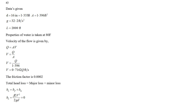
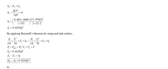
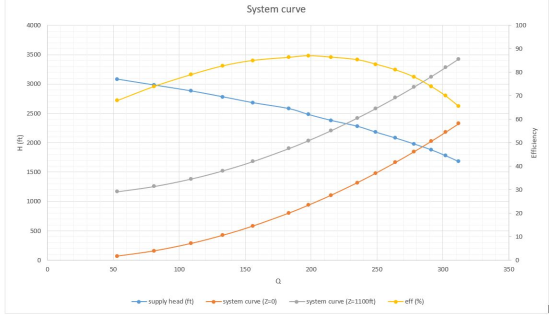
A turbo pump transfers water from tank 1 to tank to tank 2 as shown in...
 A turbo pump transfers water from tank 1 to tank to tank 2 as
shown in the picture below. The diameter of the piping system is D=
4in and the total length of pipes is L=620 ft. the elevation
difference is Z1-Z2= 30ft. Use the chart for KL values.
a) determine the flow rate (Q)
b) power of the pump in HP
Note that you can write out both mass balance equation and energy equation of the head form for...
A turbo pump transfers water from tank 1 to tank to tank 2 as
shown in the picture below. The diameter of the piping system is D=
4in and the total length of pipes is L=620 ft. the elevation
difference is Z1-Z2= 30ft. Use the chart for KL values.
a) determine the flow rate (Q)
b) power of the pump in HP
Note that you can write out both mass balance equation and energy equation of the head form for...
A pump transports water from Tank 1 to Tank 2 through a constant-diameter piping system as...
 A pump transports water from Tank 1 to Tank 2 through a constant-diameter piping system as shown below (not to scale). The flow rate is controlled by two gate valves, the gate valve I controls the main pipeline, while the gate valve II controls the loop line from T-joint A to T-joint B. All pipes are galvanized steel pipe of diameter D = 4 in. It has a total length of Li2= 620 ft from tank 1 to tank 2....
 4.45 A two-tank pump/pipe system has a head requirement of 23.4 ft at a flow rate of 100 gpm. The elevation difference between the fluid surfaces in the tanks is 10 ft. The pump is a Bell & Gossett Series e-80 Model 2.5x2.5x9C operating at 1170 rpm with a 7.5-inch impeller. a. Develop an cquation for the system curve. b. Use a computer program to develop an equation for the 7.5-inch impeller using data read from the pump performance curve...
 Problem #3: The performance data for a centrifugal water pump are shown in Table P14-31 for water at 20°c (Lpm = liters per minute). (a) For each row of data, calculate the pump efficiency (percent). Show all units. (b) Estimate the volume flow rate (Lpm) and net head (m) at the BEP of the pump.(c) Plot the pump's performance data: H, bhp, and pump efficiency as function of volume flow rate. H bhp Lpm) (m) (W) 0.0 47.5 133 6.0...
 08 % Problem 4 (25 points) A 38-in pump is installed for the system below. The pipe (100-cm diameter) has a friction factor of 0.012 and a total length of 20 km. Given that Ke = 0.5 (pipe entrance) and Ke = 1.0 (pipe exit). For water at 80 degrees Fahrenheit, estimate the flow rate (in gpm), the power required (in horsepower, HP), and the net positive suction head required (in ft) to avoid cavitation for the system when the...
 Project-Design Problem: A family of water pumps produced by a given pump manufacturer have performance and efficiency curves that can be characterized by the following dimensionless equations: Pump head 6 = 6.04-1616 where and 5 nD Pump efficiency n = 705-91,5006 where n = (power to water) / (elect power input) In the above equations, is the dimensionless pump head and is the dimensionless volumetric flow rate. h, is the pump head, n is the pump shaft/impeller rotation rate, and...
 3. A pump is to be used to pump water from the lower re servoir at an elevation of 10 ft The pump has a characteristic curve ft up to a reservoir shown in the graph below. What will be the volumetric flow rate of the water in this system? Elevation- 35 ft L- 50 t D-10 in -0.020 L-950 ft rid- Elevation 20A D-10 i -0.020 Elevation-15ft 80 60 40 Pump curve 20 1000 2000 3000 4000 5000 O,...
 A 60 horsepower pump is used to move water from a large reservoir to another at a higher elevation. Measured data show that the head loss from station 1 to 2 can be calculated from hloss= cV2 where V is the fluid velocity in the pipeline and c is a constant Calculate the volumetric flow rate, Q, if c=2 s2/ft, d=10 in., h=50 ft , and npump=0.85 h Pump
A 60 horsepower pump is used to move water from a...
A 60 horsepower pump is used to move water from a large reservoir to another at a higher elevation. Measured data show that the head loss from station 1 to 2 can be calculated from hloss= cV2 where V is the fluid velocity in the pipeline and c is a constant Calculate the volumetric flow rate, Q, if c=2 s2/ft, d=10 in., h=50 ft , and npump=0.85 h Pump
A 60 horsepower pump is used to move water from a...
 Mechanical Lab II. Please answer asap with clear work. Thank
you!
1. A centrifugal pump performance data are shown in the following table for water. Pump speed-2500 RPM Pa or P2 (bar) P. or Pi (bar) Volume of water(L Time (sec) Input-Power (W) -0.3 20 60 100 For this data set, calculate the following i. Pump discharge capacity Q (LUs and GPM) ii. Pump head H (m and ft) iii. Fluid power Pr (Watt) iv. Brake power Pb (Watt) v....
Mechanical Lab II. Please answer asap with clear work. Thank
you!
1. A centrifugal pump performance data are shown in the following table for water. Pump speed-2500 RPM Pa or P2 (bar) P. or Pi (bar) Volume of water(L Time (sec) Input-Power (W) -0.3 20 60 100 For this data set, calculate the following i. Pump discharge capacity Q (LUs and GPM) ii. Pump head H (m and ft) iii. Fluid power Pr (Watt) iv. Brake power Pb (Watt) v....
 A turbo pump transfers water from tank 1 to tank to tank 2 as
shown in the picture below. The diameter of the piping system is D=
4in and the total length of pipes is L=620 ft. the elevation
difference is Z1-Z2= 30ft. Use the chart for KL values.
a) determine the flow rate (Q)
b) power of the pump in HP
Note that you can write out both mass balance equation and energy equation of the head form for...
A turbo pump transfers water from tank 1 to tank to tank 2 as
shown in the picture below. The diameter of the piping system is D=
4in and the total length of pipes is L=620 ft. the elevation
difference is Z1-Z2= 30ft. Use the chart for KL values.
a) determine the flow rate (Q)
b) power of the pump in HP
Note that you can write out both mass balance equation and energy equation of the head form for...
 A pump transports water from Tank 1 to Tank 2 through a constant-diameter piping system as shown below (not to scale). The flow rate is controlled by two gate valves, the gate valve I controls the main pipeline, while the gate valve II controls the loop line from T-joint A to T-joint B. All pipes are galvanized steel pipe of diameter D = 4 in. It has a total length of Li2= 620 ft from tank 1 to tank 2....
Most questions answered within 3 hours.
-
Function 4: my-map
In CLISP define your own function that duplicates the
functionality of mapcar from...
asked 23 minutes ago -
Imagine you are progressing very well
during your job interview and you are confidently prepared to...
asked 22 minutes ago -
You have 2.50 L of a 0.450 M HCOOH and 0.550 M HCOONa buffer
solution. (Ka...
asked 25 minutes ago -
The Maxit Corporation has a standard costing system in which
variable manufacturing overhead is assigned to...
asked 43 minutes ago -
Let M = 8.00kg, m = 6.00kg, θ = 40.00, and the coefficient of
kinetic friction...
asked 59 minutes ago -
Java. For C through H True or false?
c. Primitive variables must be objects.
d. Integer...
asked 1 hour ago -
Write a program that turns a 32-bit numeric value (e.g.,
0xFFFFh) and converts it to a...
asked 1 hour ago -
A motor produces a torque of 0.25 N m at an angular velocity of
7200 revolutions...
asked 1 hour ago -
***Please answer the below java question***
Are static methods inheritable? Can they be overridden?
asked 1 hour ago -
In reaching her destination, a backpacker walks with an average
velocity of 1.13 m/s, due west....
asked 1 hour ago -
Write two C programs that run a
server program and a client program concurrently.
Server program:...
asked 1 hour ago -
Executive Program Practical Connection Assignment
Subject : Operations Security.
Assignment:
Provide a reflection of at least...
asked 1 hour ago