
Homework Answers


Add Answer to:
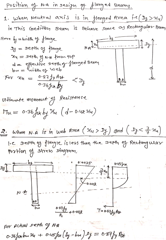
2.5 Indicate the three cases regarding the positions of neutral axis in the design of flanged...
1. For the beams shown, find the location of the neutral axis relative to the compression...
 1. For the beams shown, find the location of the neutral axis relative to the compression face, c, and the strain in the steel, Et. Is the section tension controlled, compression controlled or in the transition zone? What is the nominal moment21 strength, Mn, the strength reduction factor, , and the design moment strength, Mn 20 3-48 a) fe 3000 psi ASTM A615 Gr60 reinforcement QUESTION2 Problem 1a: What is the nominal moment strength of the beam, Mn? O245 ft-k...
2. Three charges are fixed at positions along the a-axis as positions -d, o, and +d....
 2. Three charges are fixed at positions along the a-axis as positions -d, o, and +d. The charges at -d and d are both and the charge at O is positive. (a) A positively charged object of mass m is placed on the x-axis between O and d, close to the positlicn the three charges described above do not move as a result of this new charged object, describe the mois object after it is released as it moves in...
Design a 4-bar linkage that can put the coupler link AB in the three positions shown...
 Design a 4-bar linkage that can put the coupler link AB in the three positions shown in the figure below. The length of AB is 1.25 cm. The numbers beside A1, A2 and A3 are the coordinates of pin A in the three precision positions. You will probably find it helpful to scale the drawing to a more convenient size to work on. Submit your drawing of the designed mechanism (showing it drawn clearly in all three positions as well...
The point loads are placed at the fixed positions shown in the figure and they are...
 The point loads are placed at the fixed positions shown in the figure and they are live loads. E C (centre) f = 32 Mpa fer= 3 MPa fsv = 500 MPa E = 200 GPa E = 28600 MPa a Cross section The following values are used for the question. . l = 3 m load before cracking • 12 = 2.5 m . P = 2 KN . a = 50 mm . G-5 kN/m • b =...
Three electric charges 2uC, 5uC, and -2uC are placed on the x-axis at positions -4m, 0m,...
Three electric charges 2uC, 5uC, and -2uC are placed on the x-axis at positions -4m, 0m, and 2m, respectively. What is the net force on the 5uC charge? Please explain! thank you! A. -0.017Nx B. 0.017Nx C. 0.028Nx D. 0.068Nx
The point loads are placed at the fixed positions shown in the figure and they are...
 The point loads are placed at the fixed positions shown in the figure and they are live loads. А B D E K 12 44 w * C (centre) A b f' = 32 Mpa far = 3 MPa fs, = 500 MPa E = 200 GP E = 28600 MPa A a Cross section The following values are used for the question. • 3 m load before cracking • h = 2.5 m • P=2 KN • a =...
The point loads are placed at the fixed positions shown in the figure and they are...
 The point loads are placed at the fixed positions shown in the figure and they are live loads. A B D E k w C (centre) a b f' = 32 Mpa fas= 3 MPa fsy = 500 MPa E = 200 GPa E = 28600 MPa A a Cross section The following values are used for the question. • 1 = 3 m load before cracking • 12 = 2.5 m • P = 2 kN • a =...
The point loads are placed at the fixed positions shown in the figure and they are...
 The point loads are placed at the fixed positions shown in the figure and they are live loads. А B D E K 12 44 w * C (centre) A b f' = 32 Mpa far = 3 MPa fs, = 500 MPa E = 200 GP E = 28600 MPa A a Cross section The following values are used for the question. • 3 m load before cracking • h = 2.5 m • P=2 KN • a =...
The point loads are placed at the fixed positions shown in the figure and they are...
 The point loads are placed at the fixed positions shown in the figure and they are live loads. A B D E k w C (centre) a b f' = 32 Mpa fas= 3 MPa fsy = 500 MPa E = 200 GPa E = 28600 MPa A a Cross section The following values are used for the question. • 1 = 3 m load before cracking • 12 = 2.5 m • P = 2 kN • a =...
 1. For the beams shown, find the location of the neutral axis relative to the compression face, c, and the strain in the steel, Et. Is the section tension controlled, compression controlled or in the transition zone? What is the nominal moment21 strength, Mn, the strength reduction factor, , and the design moment strength, Mn 20 3-48 a) fe 3000 psi ASTM A615 Gr60 reinforcement QUESTION2 Problem 1a: What is the nominal moment strength of the beam, Mn? O245 ft-k...
 2. Three charges are fixed at positions along the a-axis as positions -d, o, and +d. The charges at -d and d are both and the charge at O is positive. (a) A positively charged object of mass m is placed on the x-axis between O and d, close to the positlicn the three charges described above do not move as a result of this new charged object, describe the mois object after it is released as it moves in...
 Design a 4-bar linkage that can put the coupler link AB in the three positions shown in the figure below. The length of AB is 1.25 cm. The numbers beside A1, A2 and A3 are the coordinates of pin A in the three precision positions. You will probably find it helpful to scale the drawing to a more convenient size to work on. Submit your drawing of the designed mechanism (showing it drawn clearly in all three positions as well...
 The point loads are placed at the fixed positions shown in the figure and they are live loads. E C (centre) f = 32 Mpa fer= 3 MPa fsv = 500 MPa E = 200 GPa E = 28600 MPa a Cross section The following values are used for the question. . l = 3 m load before cracking • 12 = 2.5 m . P = 2 KN . a = 50 mm . G-5 kN/m • b =...
 The point loads are placed at the fixed positions shown in the figure and they are live loads. А B D E K 12 44 w * C (centre) A b f' = 32 Mpa far = 3 MPa fs, = 500 MPa E = 200 GP E = 28600 MPa A a Cross section The following values are used for the question. • 3 m load before cracking • h = 2.5 m • P=2 KN • a =...
 The point loads are placed at the fixed positions shown in the figure and they are live loads. A B D E k w C (centre) a b f' = 32 Mpa fas= 3 MPa fsy = 500 MPa E = 200 GPa E = 28600 MPa A a Cross section The following values are used for the question. • 1 = 3 m load before cracking • 12 = 2.5 m • P = 2 kN • a =...
 The point loads are placed at the fixed positions shown in the figure and they are live loads. A B D E k w C (centre) a b f' = 32 Mpa fas= 3 MPa fsy = 500 MPa E = 200 GPa E = 28600 MPa A a Cross section The following values are used for the question. • 1 = 3 m load before cracking • 12 = 2.5 m • P = 2 kN • a =...
 The point loads are placed at the fixed positions shown in the figure and they are live loads. А B D E K 12 44 w * C (centre) A b f' = 32 Mpa far = 3 MPa fs, = 500 MPa E = 200 GP E = 28600 MPa A a Cross section The following values are used for the question. • 3 m load before cracking • h = 2.5 m • P=2 KN • a =...
 The point loads are placed at the fixed positions shown in the figure and they are live loads. A B D E k w C (centre) a b f' = 32 Mpa fas= 3 MPa fsy = 500 MPa E = 200 GPa E = 28600 MPa A a Cross section The following values are used for the question. • 1 = 3 m load before cracking • 12 = 2.5 m • P = 2 kN • a =...
Most questions answered within 3 hours.
-
Learning aquatic zumba is an example of tacit knowledge. true or
false
asked 28 minutes ago -
Journalize the entries to record the following (refer to the
Chart of Accounts for exact wording...
asked 11 minutes ago -
An electron moves at 2.60×10⁶ m/s through a region in
which there is a magnetic field...
asked 8 minutes ago -
An AC generator supplies an rms voltage of 240 V at 50.0 Hz. It
is connected...
asked 10 minutes ago -
China’s income per capital maintained an 8% rate of growth in
recent decades. As a result,...
asked 13 minutes ago -
What steps would you take to institutionalize the controls you’d
select for your organization? Where do...
asked 28 minutes ago -
Table salt contains 39.33 g of sodium per 100 g of salt. The
U.S. Food and...
asked 45 minutes ago -
C&A records the following profit figures for the last six
months in Excel for a linear...
asked 42 minutes ago -
This needs to be done in c++11 and be compatible with g++
compiling
Project description:
Write...
asked 44 minutes ago -
.
NEED ANSWER ASAP
******NEW ANSWER NEVER USED BEFORE****
Write a page paper on conducting marketing...
asked 45 minutes ago -
Assume that capital markets are competitive and that the
international Fisher hypothesis holds. The one-year interest...
asked 1 hour ago -
Solid potassium phosphate is slowly added to 150 mL of a 0.0518
M calcium nitrate solution....
asked 1 hour ago