


Homework Answers

Add Answer to:
I Solve any five of following questions (show all the necessary steps) and submit until August-01-2020...
The shaft in the figure below is supported on journal bearings that do not offer any resistance t...
 The shaft in the figure below is supported on journal bearings that do not offer any resistance to axial load. The yield strength of the material is Ơ,-300 MPa and the safety factor is FS-2.5 1) 2) 3) 4) Determine the reaction at the supports. Draw the shear force, bending and torsion moment diagrams Derive an expression for the components of the stress tensor at a cross section of the shaft Neglect the shear stress due to the transverse shear...
4. For the beam and loading shown, draw the shear force and bending moment diagrams and...
 4. For the beam and loading shown, draw the shear force and bending moment diagrams and determine the maximum bending and shear force and their locations. 20 KN 40 KN B D 250 mm |--2.5 m- 3m-4-2 m 80 mm 5. For the beam and loading shown, draw the shear force and bending moment diagrams and determine the maximum bending and shear force and their locations. 50 KN
Solve in SI units. A gear reduction unit uses the countershaft shown in the figure. Gear...
 Solve in SI units.
A gear reduction unit uses the countershaft shown in the figure.
Gear A receives power from another gear with the transmitted force
FA applied at the 20ᵒ pressure angle as shown. The power is
transmitted through the shaft and delivered through gear B through
a transmitted force FB at the pressure angle shown. a) Determine
the force FB, assuming the shaft is running at a constant speed. b)
Find the magnitudes of the bearing reaction forces,...
Solve in SI units.
A gear reduction unit uses the countershaft shown in the figure.
Gear A receives power from another gear with the transmitted force
FA applied at the 20ᵒ pressure angle as shown. The power is
transmitted through the shaft and delivered through gear B through
a transmitted force FB at the pressure angle shown. a) Determine
the force FB, assuming the shaft is running at a constant speed. b)
Find the magnitudes of the bearing reaction forces,...
S4. For the beam with loading shown in Figure 4.0, a. Draw the shear and bending-moment...
 S4. For the beam with loading shown in Figure 4.0, a. Draw the shear and bending-moment diagrams for the beamA b. Deternine the maximum normal stress due to bending and shearing stress of the beams 45 kN m 16 kN m 250 mm A 75 mm 2.4 m 1.2 m Figure 4.0
1) For the loading of the beam shown below, determine the maximum normal and shear stress...
 1) For the loading of the beam shown below, determine the maximum normal and shear stress at the wall if Kt for bending is 2.7 and K, for torsion is 2.3 If we use a steel with an Sy 600 MPa, what is the "safety factor" if we only consider the maximum normal stress? Notice the bending moment, start with a cross product to determine the moment at the wall. The vector R-[0.25,0,0.3] in meters 200 mm 25-mm-dia. round rod...
PLEASE PRINT Question Four The beam has a cross section shown below and is subjected to...
 PLEASE PRINT
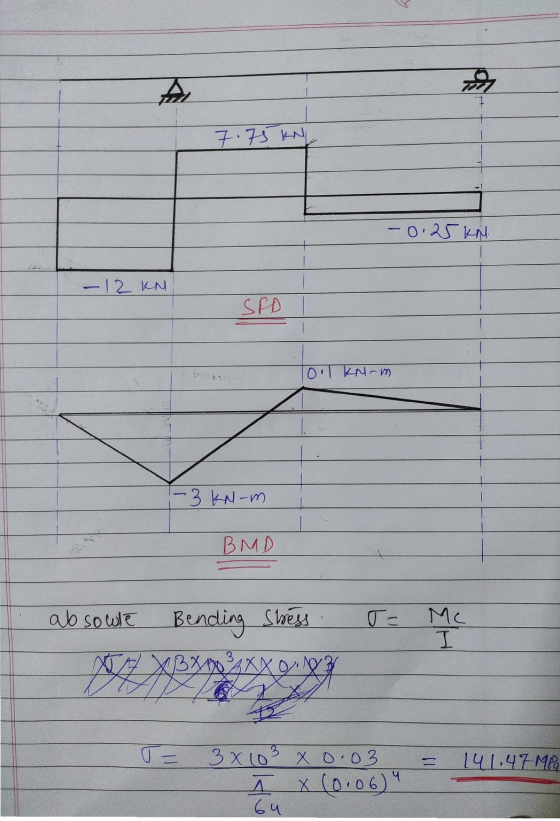
Question Four The beam has a cross section shown below and is subjected to a 1 kN load as shown. The beam AB has a length of 3 m. a) Draw the shear force and bending moment diagrams. b) Determine the maximum bending stress. c) Where is the location of the maximum stress in b) above? 30 mm 30 mm 30 mm 50 mm t 40 mm 50 m 40mm
PLEASE PRINT
Question Four The beam has a cross section shown below and is subjected to a 1 kN load as shown. The beam AB has a length of 3 m. a) Draw the shear force and bending moment diagrams. b) Determine the maximum bending stress. c) Where is the location of the maximum stress in b) above? 30 mm 30 mm 30 mm 50 mm t 40 mm 50 m 40mm
PLEASE CAN YOU SOLVE THE HOMEWORK ACCORDING TO THE ITEMS AND BY STATING WHICH ITEM THE...
 PLEASE CAN YOU SOLVE THE HOMEWORK ACCORDING TO THE ITEMS AND BY
STATING WHICH ITEM THE ANSWERS BELONG TO?
THE ANSWER IS EXPECTED AS SOON AS POSSIBLE
EMEGENCY HOMEWORK
The shaft EFG, which is running at constant speed of n (rev/min) and transmitting a power of P (kW), contains gear F. Gear F transmits torque to shaft ABCD through gear C, which drives the chain sprocket at B, transmitting a force P as shown. Sprocket B, gear C, and gear...
PLEASE CAN YOU SOLVE THE HOMEWORK ACCORDING TO THE ITEMS AND BY
STATING WHICH ITEM THE ANSWERS BELONG TO?
THE ANSWER IS EXPECTED AS SOON AS POSSIBLE
EMEGENCY HOMEWORK
The shaft EFG, which is running at constant speed of n (rev/min) and transmitting a power of P (kW), contains gear F. Gear F transmits torque to shaft ABCD through gear C, which drives the chain sprocket at B, transmitting a force P as shown. Sprocket B, gear C, and gear...
For the following beam and loading shown in the figure; all the dimensions are measured in...
 For the following beam and loading shown in the figure; all the dimensions are measured in meter. Determine: a) Draw the free body diagram. b) Draw the shear and moment diagrams using an appropriate scale, (show all calculation details) c) The maximum normal stress due to bending. 15kN 240 mm 30 mm Im 50KN 10kN/m 1 16 mm 2 350 mm A B C D E 2m 2m 2m 3m 4m Beam cross-section
Problem 1: A shaft, with a diameter of 43 mm, is shown below. On the right-hand side at location ...
 Problem 1: A shaft, with a diameter of 43 mm, is shown below. On the right-hand side at location D a wheel has a force F of 4824N applied. The diameter of this wheel is 150 mm. The torque produced by F is transmitted through the entire shaft to location A where the torque is reacted. There are no other constraints at location A. Bearings, are located at B and C, and provide radial constraint. The bearing at B also...
Problem 5.1: This is a similar problem of 5.44 in the book (7 edition), however, you...
 Problem 5.1: This is a similar problem of 5.44 in the book (7 edition), however, you are required to draw the shear and bending-moment diagrams based on the method of the left and right end internal force and moment of each section PROBLEM 5.44 Draw the shear and bending-moment diagrams for the beam and loading shown, and determine the maximum absolute value (a) of the shear, (b) of the bending moment B 4 IN Imm 0.5m. Problem 5.2: This is...
 The shaft in the figure below is supported on journal bearings that do not offer any resistance to axial load. The yield strength of the material is Ơ,-300 MPa and the safety factor is FS-2.5 1) 2) 3) 4) Determine the reaction at the supports. Draw the shear force, bending and torsion moment diagrams Derive an expression for the components of the stress tensor at a cross section of the shaft Neglect the shear stress due to the transverse shear...
 4. For the beam and loading shown, draw the shear force and bending moment diagrams and determine the maximum bending and shear force and their locations. 20 KN 40 KN B D 250 mm |--2.5 m- 3m-4-2 m 80 mm 5. For the beam and loading shown, draw the shear force and bending moment diagrams and determine the maximum bending and shear force and their locations. 50 KN
 Solve in SI units.
A gear reduction unit uses the countershaft shown in the figure.
Gear A receives power from another gear with the transmitted force
FA applied at the 20ᵒ pressure angle as shown. The power is
transmitted through the shaft and delivered through gear B through
a transmitted force FB at the pressure angle shown. a) Determine
the force FB, assuming the shaft is running at a constant speed. b)
Find the magnitudes of the bearing reaction forces,...
Solve in SI units.
A gear reduction unit uses the countershaft shown in the figure.
Gear A receives power from another gear with the transmitted force
FA applied at the 20ᵒ pressure angle as shown. The power is
transmitted through the shaft and delivered through gear B through
a transmitted force FB at the pressure angle shown. a) Determine
the force FB, assuming the shaft is running at a constant speed. b)
Find the magnitudes of the bearing reaction forces,...
 S4. For the beam with loading shown in Figure 4.0, a. Draw the shear and bending-moment diagrams for the beamA b. Deternine the maximum normal stress due to bending and shearing stress of the beams 45 kN m 16 kN m 250 mm A 75 mm 2.4 m 1.2 m Figure 4.0
 1) For the loading of the beam shown below, determine the maximum normal and shear stress at the wall if Kt for bending is 2.7 and K, for torsion is 2.3 If we use a steel with an Sy 600 MPa, what is the "safety factor" if we only consider the maximum normal stress? Notice the bending moment, start with a cross product to determine the moment at the wall. The vector R-[0.25,0,0.3] in meters 200 mm 25-mm-dia. round rod...
 PLEASE PRINT
Question Four The beam has a cross section shown below and is subjected to a 1 kN load as shown. The beam AB has a length of 3 m. a) Draw the shear force and bending moment diagrams. b) Determine the maximum bending stress. c) Where is the location of the maximum stress in b) above? 30 mm 30 mm 30 mm 50 mm t 40 mm 50 m 40mm
PLEASE PRINT
Question Four The beam has a cross section shown below and is subjected to a 1 kN load as shown. The beam AB has a length of 3 m. a) Draw the shear force and bending moment diagrams. b) Determine the maximum bending stress. c) Where is the location of the maximum stress in b) above? 30 mm 30 mm 30 mm 50 mm t 40 mm 50 m 40mm
 PLEASE CAN YOU SOLVE THE HOMEWORK ACCORDING TO THE ITEMS AND BY
STATING WHICH ITEM THE ANSWERS BELONG TO?
THE ANSWER IS EXPECTED AS SOON AS POSSIBLE
EMEGENCY HOMEWORK
The shaft EFG, which is running at constant speed of n (rev/min) and transmitting a power of P (kW), contains gear F. Gear F transmits torque to shaft ABCD through gear C, which drives the chain sprocket at B, transmitting a force P as shown. Sprocket B, gear C, and gear...
PLEASE CAN YOU SOLVE THE HOMEWORK ACCORDING TO THE ITEMS AND BY
STATING WHICH ITEM THE ANSWERS BELONG TO?
THE ANSWER IS EXPECTED AS SOON AS POSSIBLE
EMEGENCY HOMEWORK
The shaft EFG, which is running at constant speed of n (rev/min) and transmitting a power of P (kW), contains gear F. Gear F transmits torque to shaft ABCD through gear C, which drives the chain sprocket at B, transmitting a force P as shown. Sprocket B, gear C, and gear...
 For the following beam and loading shown in the figure; all the dimensions are measured in meter. Determine: a) Draw the free body diagram. b) Draw the shear and moment diagrams using an appropriate scale, (show all calculation details) c) The maximum normal stress due to bending. 15kN 240 mm 30 mm Im 50KN 10kN/m 1 16 mm 2 350 mm A B C D E 2m 2m 2m 3m 4m Beam cross-section
 Problem 1: A shaft, with a diameter of 43 mm, is shown below. On the right-hand side at location D a wheel has a force F of 4824N applied. The diameter of this wheel is 150 mm. The torque produced by F is transmitted through the entire shaft to location A where the torque is reacted. There are no other constraints at location A. Bearings, are located at B and C, and provide radial constraint. The bearing at B also...
 Problem 5.1: This is a similar problem of 5.44 in the book (7 edition), however, you are required to draw the shear and bending-moment diagrams based on the method of the left and right end internal force and moment of each section PROBLEM 5.44 Draw the shear and bending-moment diagrams for the beam and loading shown, and determine the maximum absolute value (a) of the shear, (b) of the bending moment B 4 IN Imm 0.5m. Problem 5.2: This is...
Most questions answered within 3 hours.
-
What specific indicators can point to lack of progress for
African Americans in American society?
asked 43 minutes ago -
1-The Electrons in a beam are moving at 2.7×10⁸ m/s in an
electric field of 15000...
asked 59 minutes ago -
A gas tank is a vertical cylinder. It has a radius of 1m, a
height of...
asked 1 hour ago -
Accent Software faces the following conditions. All of these
support Accent’s use of a market-penetration pricing...
asked 2 hours ago -
A mathematically inclined friend emails you the following
instructions: "Meet me in the cafeteria the first...
asked 2 hours ago -
A monopoly sells in two countries . The demand curves in the two
countries are p1...
asked 3 hours ago -
A .15kg rubber ball is bounced off a wall. Before hitting the
wall, the ball moves...
asked 4 hours ago -
A manufacturing company preparing to build a new plant is
considering three potential locations for it....
asked 4 hours ago -
B. If compound Y has approximately the same values of solubility
in toluene as compound X,...
asked 4 hours ago -
Oscar Inc. has inventory in Japan valued at 39,051,000 Yen one
year ago. One year ago...
asked 4 hours ago -
If Canada suffered from "fundamental disequilibrium," and its
government choose not to devalue its currency, a...
asked 5 hours ago -
4. How many input & output Key Value Pairs are passed into,
and emitted out of...
asked 5 hours ago