
Homework Answers

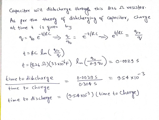
![Question (2) As per the theory of charging of capacitor charge of capacitor at time t is given by q = EC [- et/RC] q=% [l-et](http://img.homeworklib.com/questions/b2de7490-f990-11ea-95b8-cde969ed6ea5.png?x-oss-process=image/resize,w_560)
Add Answer to:
Question 1 1 pts Consider the RC circuit below with a 9V emf battery. At first...
ln the figure below you see a circuit with a battery (V), a capacitor (C), and...
 ln the figure below you see a circuit with a battery (V), a
capacitor (C), and two resistors (R1 and R2). The circuit has a
switch that can be in two positions: switched to touch point A or
switched to touch point B. By setting first the switch to A you can
charge the capacitor, and then switching it to B you discharge the
capacitor through the resistor. (This is the simple mechanism
behind a camera flash, you can imagine...
ln the figure below you see a circuit with a battery (V), a
capacitor (C), and two resistors (R1 and R2). The circuit has a
switch that can be in two positions: switched to touch point A or
switched to touch point B. By setting first the switch to A you can
charge the capacitor, and then switching it to B you discharge the
capacitor through the resistor. (This is the simple mechanism
behind a camera flash, you can imagine...
Hello can you help me in this question please? Question 2.a (20 pts) RC Circuit: The...
 Hello can you help me in this question please?
Question 2.a (20 pts) RC Circuit: The emf of the battery in the circuit is e = 12 V and the capacitance is C = 2 pF. The resistances are R, = 4.00, R2 = 2.00, R3 = 6:00 and R = 2.0. The switch is closed at time t = 0 after remaining open for a long time R w (5 pts) a) Find the currents at each resistor immidiately...
Hello can you help me in this question please?
Question 2.a (20 pts) RC Circuit: The emf of the battery in the circuit is e = 12 V and the capacitance is C = 2 pF. The resistances are R, = 4.00, R2 = 2.00, R3 = 6:00 and R = 2.0. The switch is closed at time t = 0 after remaining open for a long time R w (5 pts) a) Find the currents at each resistor immidiately...
Question 3 2 pts In the circuit shown below, the emf of the battery E =17...
 Question 3 2 pts In the circuit shown below, the emf of the battery E =17 volts; the resistors have values R1 = 196 12 and R2 = 145 N2; and the capacitors have capacitances C1 = 4 uF (microfarads) and C2 = 4 MF. After the switch has been closed for a long time, what is the charge, in uC (microcoulumbs) to the nearest uč, on capacitor 1 (C1)? S CE ES w C2 RE w R
Consider the RC circuit in the figure below. The switch was at position a for a long period of time and it is suddenly...
 Consider the RC circuit in the figure below. The switch was at
position a for a long period of time and it is
suddenly switched to position b at time t =
0.For
each statement select True or False.1. The current through the resistor equals the current across the
capacitor at all times.2. In the instant after the switch is thrown the current across the
capacitor is zero.3. In the instant after the switch is thrown the voltage across the...
Consider the RC circuit in the figure below. The switch was at
position a for a long period of time and it is
suddenly switched to position b at time t =
0.For
each statement select True or False.1. The current through the resistor equals the current across the
capacitor at all times.2. In the instant after the switch is thrown the current across the
capacitor is zero.3. In the instant after the switch is thrown the voltage across the...
Consider the RC circuit shown in the figure at the right. Notice that one only needs...
 Consider the RC circuit shown in the figure at the right. Notice that one only needs to move the switch from connecting to a to connecting to b in order go from charging the capacitor to discharging the capacitor. In the circuit to shown, R1-6.00 MΩ R,-9.00 Mov-27.0 V Initially the switch is left connected to b for a very long time. Answer the following five questions C=2.00 μF RI ih. y12pts.] When discharging, does the current flow through the...
In the circuit shown in the figure (Figure 1) , C=5.90?F, E=28.0V, and the emf has...
In the circuit shown in the figure (Figure 1) , C=5.90?F, E=28.0V, and the emf has negligible resistance. Initially the capacitor is uncharged and the switch S is in position 1. The switch is then moved to position 2, so that the capacitor begins to charge. a) What will be the charge on the capacitor a long time after the switch is moved to position 2? b) After the switch has been in position 2 for 3.00 ms, the charge...
1) Consider the circuit above: Suppose the switch S has been in position 1 for a...
 1) Consider the circuit above: Suppose the switch S has been in position 1 for a long time. At time t=0 the switch it is moved to position 2. Then at a time t = T the capacitor has lost one half of its total charge. If the resistor R is replaced with a resistor with resistance 2R and the capacitor is recharged, how long would it take for capacitor to lose half of its total charge? 2T От
Consider a series circuit containing a resistor of resistance R and a capacitor of capacitance C connected to a source of EMF E with negligible internal resistance.
 Consider a series circuit containing a resistor of resistance R and a capacitor of capacitance C connected to a source of EMF E with negligible internal resistance. The wires are also assumed to have zero resistance. Initially, the switch is open and the capacitor discharged. (Figure 1)A Immediately after the switch is closed, what is the voltage across the capacitor?B Complete previous part(s) C Immediately after the switch is closed, what is the direction of the current in the circuit? E Eventually,...
The figure below shows a circuit consisting of a 12.0V battery in series with an inductor...
 The figure below shows a circuit consisting of a 12.0V battery in series with an inductor with inductance - 11.0 H, a resistor with resistance R - 2.500, and a switch, Initially open, (a) After the switch is closed, what is the maximum current in A) that will flow through the circuit? (b) What is the time constant (ins) of the circuit? (c) After the switch is closed, how much time (ins) does it take for the current to reach...
Learning Goal: To understand the dynamics of a series R-C circuit. Consider a series circuit containing...
 Learning Goal: To understand the dynamics of a series R-C circuit. Consider a series circuit containing a resistor of resistance R and a capacitor of capacitance C connected to a source of EMF ε with negligible internal resistance. The wires are also assumed to have zero resistance. Initially, the switch is open and the capacitor discharged. (Figure 1)Let us try to understand the processes that take place after the switch is closed. The charge of the capacitor, the current in...
 ln the figure below you see a circuit with a battery (V), a
capacitor (C), and two resistors (R1 and R2). The circuit has a
switch that can be in two positions: switched to touch point A or
switched to touch point B. By setting first the switch to A you can
charge the capacitor, and then switching it to B you discharge the
capacitor through the resistor. (This is the simple mechanism
behind a camera flash, you can imagine...
ln the figure below you see a circuit with a battery (V), a
capacitor (C), and two resistors (R1 and R2). The circuit has a
switch that can be in two positions: switched to touch point A or
switched to touch point B. By setting first the switch to A you can
charge the capacitor, and then switching it to B you discharge the
capacitor through the resistor. (This is the simple mechanism
behind a camera flash, you can imagine...
 Hello can you help me in this question please?
Question 2.a (20 pts) RC Circuit: The emf of the battery in the circuit is e = 12 V and the capacitance is C = 2 pF. The resistances are R, = 4.00, R2 = 2.00, R3 = 6:00 and R = 2.0. The switch is closed at time t = 0 after remaining open for a long time R w (5 pts) a) Find the currents at each resistor immidiately...
Hello can you help me in this question please?
Question 2.a (20 pts) RC Circuit: The emf of the battery in the circuit is e = 12 V and the capacitance is C = 2 pF. The resistances are R, = 4.00, R2 = 2.00, R3 = 6:00 and R = 2.0. The switch is closed at time t = 0 after remaining open for a long time R w (5 pts) a) Find the currents at each resistor immidiately...
 Question 3 2 pts In the circuit shown below, the emf of the battery E =17 volts; the resistors have values R1 = 196 12 and R2 = 145 N2; and the capacitors have capacitances C1 = 4 uF (microfarads) and C2 = 4 MF. After the switch has been closed for a long time, what is the charge, in uC (microcoulumbs) to the nearest uč, on capacitor 1 (C1)? S CE ES w C2 RE w R
 Consider the RC circuit in the figure below. The switch was at
position a for a long period of time and it is
suddenly switched to position b at time t =
0.For
each statement select True or False.1. The current through the resistor equals the current across the
capacitor at all times.2. In the instant after the switch is thrown the current across the
capacitor is zero.3. In the instant after the switch is thrown the voltage across the...
Consider the RC circuit in the figure below. The switch was at
position a for a long period of time and it is
suddenly switched to position b at time t =
0.For
each statement select True or False.1. The current through the resistor equals the current across the
capacitor at all times.2. In the instant after the switch is thrown the current across the
capacitor is zero.3. In the instant after the switch is thrown the voltage across the...
 Consider the RC circuit shown in the figure at the right. Notice that one only needs to move the switch from connecting to a to connecting to b in order go from charging the capacitor to discharging the capacitor. In the circuit to shown, R1-6.00 MΩ R,-9.00 Mov-27.0 V Initially the switch is left connected to b for a very long time. Answer the following five questions C=2.00 μF RI ih. y12pts.] When discharging, does the current flow through the...
 1) Consider the circuit above: Suppose the switch S has been in position 1 for a long time. At time t=0 the switch it is moved to position 2. Then at a time t = T the capacitor has lost one half of its total charge. If the resistor R is replaced with a resistor with resistance 2R and the capacitor is recharged, how long would it take for capacitor to lose half of its total charge? 2T От
 The figure below shows a circuit consisting of a 12.0V battery in series with an inductor with inductance - 11.0 H, a resistor with resistance R - 2.500, and a switch, Initially open, (a) After the switch is closed, what is the maximum current in A) that will flow through the circuit? (b) What is the time constant (ins) of the circuit? (c) After the switch is closed, how much time (ins) does it take for the current to reach...
Most questions answered within 3 hours.
-
An empty test tube weighs 15.923 grams. Then,
MgCl2•6H2O is added into the test tube. After...
asked 29 minutes ago -
Please answer true or false. Words
cannot be changed or added in to make it true...
asked 27 minutes ago -
(a) A piston at 6.1 atm contains a gas that occupies a volume of
3.5 L....
asked 28 minutes ago -
Assume memory access is 10 units of time and disk access is
10000 units of time....
asked 47 minutes ago -
1. Are all good samples random?
2. Magazines often report surveys giving statistics such as “63%...
asked 1 hour ago -
Under all the various types of market structures, firms
must eventually earn some economic profits for...
asked 55 minutes ago -
Consider the following fitness regime for a single locus trait
with two co-dominant alleles: w11 =...
asked 59 minutes ago -
A large cable company reports the following.
80% of its customers subscribe to its cable TV...
asked 1 hour ago -
Please answer the question in brief.
Discuss the role of ERP in organizations. Are ERP tools...
asked 1 hour ago -
Discuss the pros and cons of collaborative software such
as SameTime. Does it increase productivity? What...
asked 1 hour ago -
Buying your in-laws a gift because it’s expected is
due to the ____________ motive of gift-giving....
asked 1 hour ago -
Calculate the expected value, the variance, and the standard
deviation of the given random variable X....
asked 1 hour ago