 All calculations need the
counting processand Free Body Diagram.
All calculations need the
counting processand Free Body Diagram.
Homework Answers
Add Answer to:
All calculations need the
counting processand Free Body Diagram.
1. Determine the normal force, shear force,...
All calculations need the counting processand Free Body Diagram. 1. Determine the normal force, shear force,...
 All calculations need the counting processand Free Body Diagram.
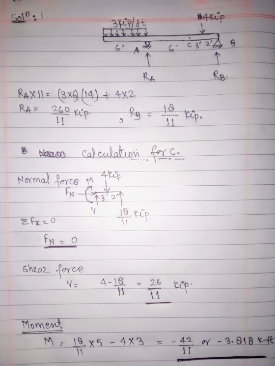
1. Determine the normal force, shear force, and moment at point C. (15 Points). 4 kip 3 kip/ft B А С - 3 ft --2 ft- 6 ft + 6 ft
All calculations need the counting processand Free Body Diagram.
1. Determine the normal force, shear force, and moment at point C. (15 Points). 4 kip 3 kip/ft B А С - 3 ft --2 ft- 6 ft + 6 ft
All calculations need the counting processand Free Body Diagram. 3. Determine the maximum force P that...
 All calculations need the
counting processand Free Body Diagram.
3. Determine the maximum force P that can be applied without causing movement of the 300-lb crate that has a center of gravity at G. The coefficient of static friction at the floor is Is = 0.4. (20 Points) 1.5 ft 1.5 ft 2.5 ft P- 'T 4.5 ft 3.5 ft
All calculations need the
counting processand Free Body Diagram.
3. Determine the maximum force P that can be applied without causing movement of the 300-lb crate that has a center of gravity at G. The coefficient of static friction at the floor is Is = 0.4. (20 Points) 1.5 ft 1.5 ft 2.5 ft P- 'T 4.5 ft 3.5 ft
PROBLEM 3 (25%) For the problem shown below, the free body diagram (FBD) is superimposed showing...
 PROBLEM 3 (25%) For the problem shown below, the free body diagram (FBD) is superimposed showing the reactions forces (the reaction forces are given). Ax = 0; Ay = 9 kip, Cy = 33 kip 1. Draw the shear force diagram. Identify values at kink points (no equations required). 2. Draw the bending moment diagram. Identify values at kink points (no equations required). 3. Determine the value of the maximum positive moment in the beam (Mmax). 4. Compute the vertical...
Question 3:: Draw the free body diagram and calculate the reactions. Determine the internal normal force,...
 Question 3:: Draw the free body diagram and calculate the reactions. Determine the internal normal force, shear force, and moments at points C. Point A is a cantilever support. Type your answers and intermediate calculations on the screen on the blackboard. tokw rrm 6
1. (28 pts) A cantilever beam is subjected to the loads as shown in the figure....
 1. (28 pts) A cantilever beam is subjected to the loads as shown in the figure. Va) Draw a free-body diagram and determine the supports at point 0. b) Draw shear and moment diagrams and find the values at key points (i.e. x = 0, 6 and 10 ft). If possible, please show your calculations. c) Find shear force V(x) and bending moment M(x) for () <x<6 ft. 12 10 kip 2 kip/ft skip سے 40 kip.lt 611 4 11...
Determine the normal force at section passing through pointD.- Determine the shear force...
 - Determine the normal force at section passing through point
D.- Determine the shear force at section passing through point
D.-Determine the moment at section passing through point D.-Determine the normal force at section passing through point
E.-Determine the shear force at section passing through point
E.-Determine the moment at section passing through point E.Consider the beam shown in (Figure 1). Suppose P = 6 kip, w = 1.6 kip/ft. Point E is just to the right of the 6-kip...
- Determine the normal force at section passing through point
D.- Determine the shear force at section passing through point
D.-Determine the moment at section passing through point D.-Determine the normal force at section passing through point
E.-Determine the shear force at section passing through point
E.-Determine the moment at section passing through point E.Consider the beam shown in (Figure 1). Suppose P = 6 kip, w = 1.6 kip/ft. Point E is just to the right of the 6-kip...
2. Draw Shear Force and Bending Moment Diagram (use your preferred method). Determine Maximum Ten...
 2. Draw Shear Force and Bending Moment Diagram (use your preferred method). Determine Maximum Tensile and Compressive Stresses due to bending, state where on the beam these occur. For the mid-point between A and B, determine shear stress at neutral axis; 2" from the top of the flange; at the junction between web and flange and on the top of the flange for the cross-section. Plot of the bending stress and shear stress distribution diagram across the cross section of...
Use the graphical method to construct the shear-force and bending-moment diagrams for the beam shown. Let...
 Use the graphical method to construct the shear-force and bending-moment diagrams for the beam shown. Let a=4.0 ft, b=9.0 ft, c=5.0 ft, d=4.0 ft, w = 8 kips/ft and P = 75 kips. Construct the shear-force and bending-moment diagrams on paper and use the results to answer the questions in the subsequent parts of this GO exercise. W X A B C D E a b с For this loading, calculate the reaction forces Ay and Ey acting on the...
Determine the normal force, shear force, and moment at point C. Take that w = 2.6 kip/ft .(Figure 1)
 Determine the normal force, shear force, and moment at point C. Take that w = 2.6 kip/ft .(Figure 1)
 All calculations need the counting processand Free Body Diagram.
1. Determine the normal force, shear force, and moment at point C. (15 Points). 4 kip 3 kip/ft B А С - 3 ft --2 ft- 6 ft + 6 ft
All calculations need the counting processand Free Body Diagram.
1. Determine the normal force, shear force, and moment at point C. (15 Points). 4 kip 3 kip/ft B А С - 3 ft --2 ft- 6 ft + 6 ft
 All calculations need the
counting processand Free Body Diagram.
3. Determine the maximum force P that can be applied without causing movement of the 300-lb crate that has a center of gravity at G. The coefficient of static friction at the floor is Is = 0.4. (20 Points) 1.5 ft 1.5 ft 2.5 ft P- 'T 4.5 ft 3.5 ft
All calculations need the
counting processand Free Body Diagram.
3. Determine the maximum force P that can be applied without causing movement of the 300-lb crate that has a center of gravity at G. The coefficient of static friction at the floor is Is = 0.4. (20 Points) 1.5 ft 1.5 ft 2.5 ft P- 'T 4.5 ft 3.5 ft
 PROBLEM 3 (25%) For the problem shown below, the free body diagram (FBD) is superimposed showing the reactions forces (the reaction forces are given). Ax = 0; Ay = 9 kip, Cy = 33 kip 1. Draw the shear force diagram. Identify values at kink points (no equations required). 2. Draw the bending moment diagram. Identify values at kink points (no equations required). 3. Determine the value of the maximum positive moment in the beam (Mmax). 4. Compute the vertical...
 PROBLEM 3 (25%) For the problem shown below, the free body diagram (FBD) is superimposed showing the reactions forces (the reaction forces are given). Ax = 0; Ay = 9 kip, Cy = 33 kip 1. Draw the shear force diagram. Identify values at kink points (no equations required). 2. Draw the bending moment diagram. Identify values at kink points (no equations required). 3. Determine the value of the maximum positive moment in the beam (Mmax). 4. Compute the vertical...
 Question 3:: Draw the free body diagram and calculate the reactions. Determine the internal normal force, shear force, and moments at points C. Point A is a cantilever support. Type your answers and intermediate calculations on the screen on the blackboard. tokw rrm 6
 1. (28 pts) A cantilever beam is subjected to the loads as shown in the figure. Va) Draw a free-body diagram and determine the supports at point 0. b) Draw shear and moment diagrams and find the values at key points (i.e. x = 0, 6 and 10 ft). If possible, please show your calculations. c) Find shear force V(x) and bending moment M(x) for () <x<6 ft. 12 10 kip 2 kip/ft skip سے 40 kip.lt 611 4 11...
 2. Draw Shear Force and Bending Moment Diagram (use your preferred method). Determine Maximum Tensile and Compressive Stresses due to bending, state where on the beam these occur. For the mid-point between A and B, determine shear stress at neutral axis; 2" from the top of the flange; at the junction between web and flange and on the top of the flange for the cross-section. Plot of the bending stress and shear stress distribution diagram across the cross section of...
 Use the graphical method to construct the shear-force and bending-moment diagrams for the beam shown. Let a=4.0 ft, b=9.0 ft, c=5.0 ft, d=4.0 ft, w = 8 kips/ft and P = 75 kips. Construct the shear-force and bending-moment diagrams on paper and use the results to answer the questions in the subsequent parts of this GO exercise. W X A B C D E a b с For this loading, calculate the reaction forces Ay and Ey acting on the...
 Determine the normal force, shear force, and moment at point C. Take that w = 2.6 kip/ft .(Figure 1)
Most questions answered within 3 hours.
-
Work of 1950 J is done by stirring a perfectly insulated beaker
containing 75 g of...
asked 28 minutes ago -
The neighborhood kids set up an outdoor lemonade stand in
Maryland in June. They find that...
asked 29 minutes ago -
9. A company has a beginning inventory of 4,000 units. The
company estimates it will sell...
asked 43 minutes ago -
A patient goes to the doctor's office with symptoms of a urinary
tract infection and provides...
asked 45 minutes ago -
When responding to the essay questions, be sure to cite any
material you obtained from a...
asked 45 minutes ago -
The energy of an electron in a 2.25-eV-deep potential well is
1.50 eV.At what distance into...
asked 47 minutes ago -
Q1:Which three evolutionary innovations are present in land
plants (but not all land plants) that allowed...
asked 49 minutes ago -
Lymphosarcoma is
extremely rare. Risk factors for the disease are largely unknown.
What kind of study...
asked 52 minutes ago -
The solubility of benzoic acid in water is:
0.29g/100mL at 20°C
6.8g/100mL at 100°C
a) What...
asked 53 minutes ago -
Which food law was passed in 1996 and changed how pesticide
residues on food were regulated...
asked 1 hour ago -
companies either hire outside programmers to
write_____ software or use their own internal developers.
asked 1 hour ago -
A magnetic dipole m(t) = m_0*cos(ωt) can be
described as current density j(r,t) = −cm(t) ×...
asked 1 hour ago