
Homework Answers
The solution of the given problem is given below
Add Answer to:
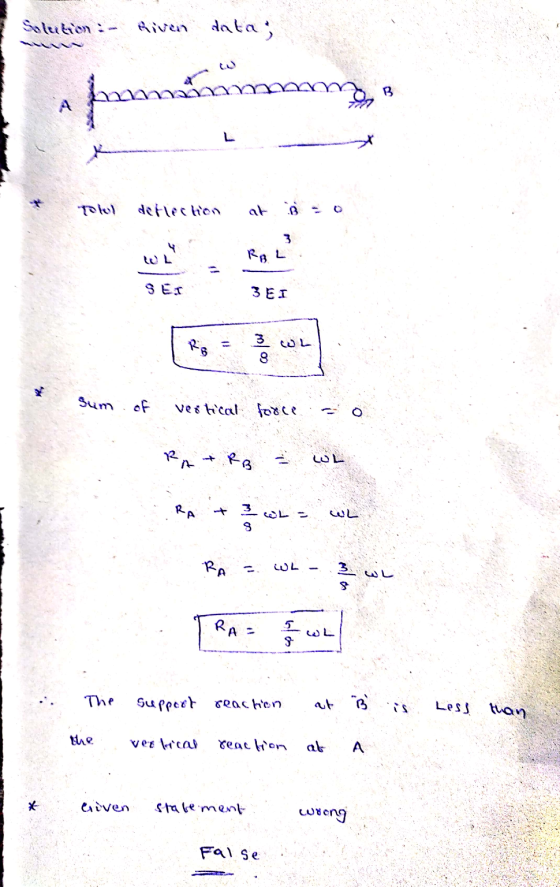
For the propped cantilever beam loaded as shown W A OB L- The vertical support reaction...
Question 13 For the propped cantilever beam loaded as shown W А OB - L- The...
 Question 13 For the propped cantilever beam loaded as shown W А OB - L- The boundary conditions for the support at B can best be described as... @X=L, DY/dX=0 @X=L, Y=0 @X=L, Y=0 and dy/dX=0 @X=L, there are no boundary conditions
Question 12 For the propped cantilever beam loaded as shown W A OB L- The boundary...
 Question 12 For the propped cantilever beam loaded as shown W A OB L- The boundary conditions for the support at A can best be described as... @X=0, Y=0 @X=0, there are no boundary conditions @X=0,dY/dX=0 @X=0, Y=0 and dY/dX=0
A propped cantilever beam is loaded as shown. Determine the reactions at A and D (positive...
 A propped cantilever beam is loaded as shown. Determine the reactions at A and D (positive if the force is up and if the moment is counterclockwise) for the beam. Assume EI = 8.1 x 10⁶ lb-inf. Assume L 66 in., w 29 lb/in., P-440 lb Answers: lb, MA--37752 Ib-in A 1144 572 D= lb.
A propped cantilever beam is loaded as shown. Assume that EI = 250,000 kN-m2, and use...
 A propped cantilever beam is loaded as shown. Assume that
EI = 250,000 kN-m2, and use discontinuity
functions to determine
(a) the reactions at A and B.
(b) the beam deflection at C.
The reaction forces are positive if up and negative if down. The
reaction moment is positive if counterclockwise and negative if
clockwise.
Assume LAB = 5.4 m, LBC =
2.9 m, MC = 700 kN-m.
V Mc X A B LAB LBC Answers: (a) Ay = KN...
A propped cantilever beam is loaded as shown. Assume that
EI = 250,000 kN-m2, and use discontinuity
functions to determine
(a) the reactions at A and B.
(b) the beam deflection at C.
The reaction forces are positive if up and negative if down. The
reaction moment is positive if counterclockwise and negative if
clockwise.
Assume LAB = 5.4 m, LBC =
2.9 m, MC = 700 kN-m.
V Mc X A B LAB LBC Answers: (a) Ay = KN...
The cantilever beam below is loaded as shown. The complete FBD with support reaction is given...
 The cantilever beam below is loaded as shown. The complete FBD with support reaction is given as the first step of the solution. MA-17.75 kN-m 0.5 kN/m 4 kN-m A-O 1 A-1.5 KN 2 m 3 m 2 m 5 m ND: a) Draw the shear (V) and moment (M) diagrams. b) Label all significant values on the shear and moment diagrams (i.e. at Om, 2m, 5m, 7m)
I-beam loaded as a cantilever beam 2. An I-beam is loaded as a cantilever beam as shown below. The cross-section of the...
 I-beam loaded as a cantilever beam
2. An I-beam is loaded as a cantilever beam as shown below. The cross-section of the beam is also shown. Indicate on both illustrations, by circling and labeling, the location of the maximum tensile stress and the maximum compressive stress.
2. An I-beam is loaded as a cantilever beam as shown below. The cross-section of the beam is also shown. Indicate on both illustrations, by circling and labeling, the location of the maximum tensile...
I-beam loaded as a cantilever beam
2. An I-beam is loaded as a cantilever beam as shown below. The cross-section of the beam is also shown. Indicate on both illustrations, by circling and labeling, the location of the maximum tensile stress and the maximum compressive stress.
2. An I-beam is loaded as a cantilever beam as shown below. The cross-section of the beam is also shown. Indicate on both illustrations, by circling and labeling, the location of the maximum tensile...
1. A cantilever beam of constant AE and El is loaded as shown in the figure...
 1. A cantilever beam of constant AE and El is loaded as shown in the figure below. Determine the vertical and horizontal deflections and the angular rotation of the free end, considering the effects of normal force and benign moment. Employ Castigliano's Theorem.
A cantilever beam with a l-in-diameter round cross section is loaded at the tip with a...
 A cantilever beam with a l-in-diameter round cross section is loaded at the tip with a transverse force of 1,000 lbf, as shown in the figure. The cross section at the wall is alsa shown, with labeled points.A at the top, B at the center, and C at the midpoint between A and B. 1,000 lbf tm 1 in dia. Cross section at the wall References
For the beam and loading shown, determine the vertical reaction at the support located at A....
 For the beam and loading shown, determine the vertical reaction
at the support located at A. The distributed load w = 10kN/m, and
the beam W 310 x 52 has a moment of inertia Ix = 119 x
106 mm4 and modulus of elasticity E = 200
GPa
ЕВ с 2 m- 4 m
For the beam and loading shown, determine the vertical reaction
at the support located at A. The distributed load w = 10kN/m, and
the beam W 310 x 52 has a moment of inertia Ix = 119 x
106 mm4 and modulus of elasticity E = 200
GPa
ЕВ с 2 m- 4 m
 Question 13 For the propped cantilever beam loaded as shown W А OB - L- The boundary conditions for the support at B can best be described as... @X=L, DY/dX=0 @X=L, Y=0 @X=L, Y=0 and dy/dX=0 @X=L, there are no boundary conditions
 Question 12 For the propped cantilever beam loaded as shown W A OB L- The boundary conditions for the support at A can best be described as... @X=0, Y=0 @X=0, there are no boundary conditions @X=0,dY/dX=0 @X=0, Y=0 and dY/dX=0
 A propped cantilever beam is loaded as shown. Determine the reactions at A and D (positive if the force is up and if the moment is counterclockwise) for the beam. Assume EI = 8.1 x 10⁶ lb-inf. Assume L 66 in., w 29 lb/in., P-440 lb Answers: lb, MA--37752 Ib-in A 1144 572 D= lb.
 A propped cantilever beam is loaded as shown. Assume that
EI = 250,000 kN-m2, and use discontinuity
functions to determine
(a) the reactions at A and B.
(b) the beam deflection at C.
The reaction forces are positive if up and negative if down. The
reaction moment is positive if counterclockwise and negative if
clockwise.
Assume LAB = 5.4 m, LBC =
2.9 m, MC = 700 kN-m.
V Mc X A B LAB LBC Answers: (a) Ay = KN...
A propped cantilever beam is loaded as shown. Assume that
EI = 250,000 kN-m2, and use discontinuity
functions to determine
(a) the reactions at A and B.
(b) the beam deflection at C.
The reaction forces are positive if up and negative if down. The
reaction moment is positive if counterclockwise and negative if
clockwise.
Assume LAB = 5.4 m, LBC =
2.9 m, MC = 700 kN-m.
V Mc X A B LAB LBC Answers: (a) Ay = KN...
 The cantilever beam below is loaded as shown. The complete FBD with support reaction is given as the first step of the solution. MA-17.75 kN-m 0.5 kN/m 4 kN-m A-O 1 A-1.5 KN 2 m 3 m 2 m 5 m ND: a) Draw the shear (V) and moment (M) diagrams. b) Label all significant values on the shear and moment diagrams (i.e. at Om, 2m, 5m, 7m)
 The cantilever beam below is loaded as shown. The complete FBD with support reaction is given as the first step of the solution. MA-17.75 kN-m 0.5 kN/m 4 kN-m A-O 1 A-1.5 KN 2 m 3 m 2 m 5 m ND: a) Draw the shear (V) and moment (M) diagrams. b) Label all significant values on the shear and moment diagrams (i.e. at Om, 2m, 5m, 7m)
 I-beam loaded as a cantilever beam
2. An I-beam is loaded as a cantilever beam as shown below. The cross-section of the beam is also shown. Indicate on both illustrations, by circling and labeling, the location of the maximum tensile stress and the maximum compressive stress.
2. An I-beam is loaded as a cantilever beam as shown below. The cross-section of the beam is also shown. Indicate on both illustrations, by circling and labeling, the location of the maximum tensile...
I-beam loaded as a cantilever beam
2. An I-beam is loaded as a cantilever beam as shown below. The cross-section of the beam is also shown. Indicate on both illustrations, by circling and labeling, the location of the maximum tensile stress and the maximum compressive stress.
2. An I-beam is loaded as a cantilever beam as shown below. The cross-section of the beam is also shown. Indicate on both illustrations, by circling and labeling, the location of the maximum tensile...
 1. A cantilever beam of constant AE and El is loaded as shown in the figure below. Determine the vertical and horizontal deflections and the angular rotation of the free end, considering the effects of normal force and benign moment. Employ Castigliano's Theorem.
 A cantilever beam with a l-in-diameter round cross section is loaded at the tip with a transverse force of 1,000 lbf, as shown in the figure. The cross section at the wall is alsa shown, with labeled points.A at the top, B at the center, and C at the midpoint between A and B. 1,000 lbf tm 1 in dia. Cross section at the wall References
 For the beam and loading shown, determine the vertical reaction
at the support located at A. The distributed load w = 10kN/m, and
the beam W 310 x 52 has a moment of inertia Ix = 119 x
106 mm4 and modulus of elasticity E = 200
GPa
ЕВ с 2 m- 4 m
For the beam and loading shown, determine the vertical reaction
at the support located at A. The distributed load w = 10kN/m, and
the beam W 310 x 52 has a moment of inertia Ix = 119 x
106 mm4 and modulus of elasticity E = 200
GPa
ЕВ с 2 m- 4 m
Most questions answered within 3 hours.
-
Sulfuric acid (250.0mL) is titrated with 176.5 mL 2.4 M NaOH to
an equivalence point (the...
asked 5 minutes ago -
The quality control manager of a cookie company is inspecting a
batch of chocolate-chip cookies that...
asked 6 minutes ago -
How can we identify what the horizontal force is when looking at
a merry go round?...
asked 39 minutes ago -
While Dime Community Bank is based in Brooklyn; management has
decided to focus its lending activity...
asked 1 hour ago -
1) Earnings functions, whereby the log of earnings is regressed
on years of education, years of...
asked 37 minutes ago -
Bruno Corporation is involved in the business of injection
molding of plastics. It is considering the...
asked 42 minutes ago -
What would be the vapor pressure of water at 96°C above a
solution made by dissolving...
asked 57 minutes ago -
Hydration of norbornene
Write the reaction. Discuss the intermediate. Explain how the
equilibrium in the reaction...
asked 1 hour ago -
Suppose that a party wanted to enter an FRA that expires in 42
days and is...
asked 1 hour ago -
ABC Ltd. estimated that a new store requires an initial
investment of $800,000. This new store...
asked 1 hour ago -
1. Review the Nike’s marketing strategy. You must include the
company’s target market, possible market segmentation,...
asked 1 hour ago -
One of the major advantages of ______________ is to enhance
security for private networks by keeping...
asked 1 hour ago