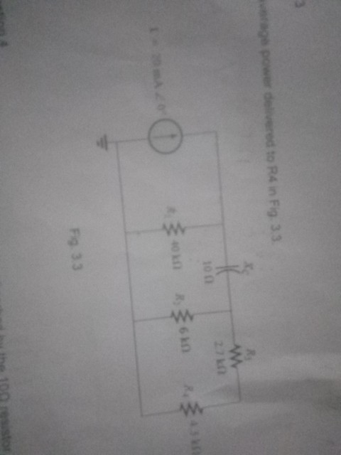
Find the average Power delivered to R4
Homework Answers


Add Answer to:
Find the average Power delivered to R4
rage power delivered to R4 in Fig. 33 27...
8. Find the complex power delivered by v, to the network in Fig. 11.69 Let v,...
 8. Find the complex power delivered by v, to the network in Fig. 11.69 Let v, 100 cos 2000r V 209
AL SDEMATIC A plot of the power delivered to Re in Fig. 9.120 for a range...
 AL SDEMATIC A plot of the power delivered to Re in Fig. 9.120 for a range of values for R extending from 0 to 30 n FIG. 9.122 plot generated appears as a listing at the bottom left of the W/RL) Before leaving the subject, we should mention that the pou can be determined in more ways than one from the Add Trac box. For example, first enter a minus sign because of the resu rent direction through the resistor,...
For the circuits shown find the average power and reactive power delivered by the source. 3.2...
 For the circuits shown find the average power and reactive power delivered by the source. 3.2 o.SH
For the system shown in Figure 2: a) Find IS. b) Find the average power delivered...
 For the system shown in Figure 2: a) Find
IS. b) Find the average power delivered to each element. c) Find
the reactive power for each element. d) Find the apparent power for
each element. e) Find PT, QT, ST. f) Sketch the power triangle.
Figure 2 g) Find the power factor seen by the source E.
Problem 2 For the system shown in Figure 2: a) Find Is. R3 b) Find the average power delivered to each element c)...
For the system shown in Figure 2: a) Find
IS. b) Find the average power delivered to each element. c) Find
the reactive power for each element. d) Find the apparent power for
each element. e) Find PT, QT, ST. f) Sketch the power triangle.
Figure 2 g) Find the power factor seen by the source E.
Problem 2 For the system shown in Figure 2: a) Find Is. R3 b) Find the average power delivered to each element c)...
For the circuit in the given figure, find the average, reactive, and complex power delivered by...
 For the circuit in the given figure, find the average, reactive, and complex power delivered by the dependent voltage source. Assume V = 58 2259 V. 40 -j1 2220 v 19 v 129 2V The average power is W. The reactive power is VA. The complex power is ( ) VA
Part A Find the average power delivered by the ideal current source in the circuit in...
 Part A Find the average power delivered by the ideal current source in the circuit in the figure if ig-4 cos 5000t mA.(Figure 1) Express your answer with the appropriate units. P. Value Units igure 1 of 1 Submit Request Answer Provide Feedback 500 Ω 1000 Ω 100 mH 160 nF
Question (4 (A)In Fig. 4a, letI43s A rms, and find the average power being supplied: (a)...
 Question (4 (A)In Fig. 4a, letI43s A rms, and find the average power being supplied: (a) by the source: (b) to the 20a resistor: (c) to the load. Find the apparent power being supplied: (d) by the source: (e) to the 20 Ω resistor: (f) to the load. (g) what is the load PF? , 10.ror Ann-G) 2ο Ω_ 20 Load FIGURE 4.a 4.b, find the average power absorbed by (a) the source: (b) h of the two resistors: (e)...
20Ω 30 Ω j20Ω Fig. 1.7 In the circuit of Fig. 1.8, find the RMS phasor...
 20Ω 30 Ω j20Ω Fig. 1.7 In the circuit of Fig. 1.8, find the RMS phasor voltage V so that the 60 Ω resistor absorbs an average power of 240 W. Hence, determine the complex power delivered to each component, the complex power and the power factor delivered by voltage source. Fig. 1.8 2) P1.8
For the emitter follower of Fig. 12.2. let Vcc-10 V, 1-1 00 mA, and R.-100 Ω. If the output volta...
 For the emitter follower of Fig. 12.2. let Vcc-10 V, 1-1 00 mA, and R.-100 Ω. If the output voltage is an 8-V-peak sinusoid, find the following: (a) the power delivered to the load; (b) the average power drawn from the supplies: (c) the power-conversion efficiency. Ignore the loss in Qs and R 0 URE 02
For the emitter follower of Fig. 12.2. let Vcc-10 V, 1-1 00 mA, and R.-100 Ω. If the output voltage is an 8-V-peak sinusoid,...
For the emitter follower of Fig. 12.2. let Vcc-10 V, 1-1 00 mA, and R.-100 Ω. If the output voltage is an 8-V-peak sinusoid, find the following: (a) the power delivered to the load; (b) the average power drawn from the supplies: (c) the power-conversion efficiency. Ignore the loss in Qs and R 0 URE 02
For the emitter follower of Fig. 12.2. let Vcc-10 V, 1-1 00 mA, and R.-100 Ω. If the output voltage is an 8-V-peak sinusoid,...
 8. Find the complex power delivered by v, to the network in Fig. 11.69 Let v, 100 cos 2000r V 209
 AL SDEMATIC A plot of the power delivered to Re in Fig. 9.120 for a range of values for R extending from 0 to 30 n FIG. 9.122 plot generated appears as a listing at the bottom left of the W/RL) Before leaving the subject, we should mention that the pou can be determined in more ways than one from the Add Trac box. For example, first enter a minus sign because of the resu rent direction through the resistor,...
 For the circuits shown find the average power and reactive power delivered by the source. 3.2 o.SH
 For the system shown in Figure 2: a) Find
IS. b) Find the average power delivered to each element. c) Find
the reactive power for each element. d) Find the apparent power for
each element. e) Find PT, QT, ST. f) Sketch the power triangle.
Figure 2 g) Find the power factor seen by the source E.
Problem 2 For the system shown in Figure 2: a) Find Is. R3 b) Find the average power delivered to each element c)...
For the system shown in Figure 2: a) Find
IS. b) Find the average power delivered to each element. c) Find
the reactive power for each element. d) Find the apparent power for
each element. e) Find PT, QT, ST. f) Sketch the power triangle.
Figure 2 g) Find the power factor seen by the source E.
Problem 2 For the system shown in Figure 2: a) Find Is. R3 b) Find the average power delivered to each element c)...
 For the circuit in the given figure, find the average, reactive, and complex power delivered by the dependent voltage source. Assume V = 58 2259 V. 40 -j1 2220 v 19 v 129 2V The average power is W. The reactive power is VA. The complex power is ( ) VA
 Part A Find the average power delivered by the ideal current source in the circuit in the figure if ig-4 cos 5000t mA.(Figure 1) Express your answer with the appropriate units. P. Value Units igure 1 of 1 Submit Request Answer Provide Feedback 500 Ω 1000 Ω 100 mH 160 nF
 Question (4 (A)In Fig. 4a, letI43s A rms, and find the average power being supplied: (a) by the source: (b) to the 20a resistor: (c) to the load. Find the apparent power being supplied: (d) by the source: (e) to the 20 Ω resistor: (f) to the load. (g) what is the load PF? , 10.ror Ann-G) 2ο Ω_ 20 Load FIGURE 4.a 4.b, find the average power absorbed by (a) the source: (b) h of the two resistors: (e)...
 20Ω 30 Ω j20Ω Fig. 1.7 In the circuit of Fig. 1.8, find the RMS phasor voltage V so that the 60 Ω resistor absorbs an average power of 240 W. Hence, determine the complex power delivered to each component, the complex power and the power factor delivered by voltage source. Fig. 1.8 2) P1.8
 For the emitter follower of Fig. 12.2. let Vcc-10 V, 1-1 00 mA, and R.-100 Ω. If the output voltage is an 8-V-peak sinusoid, find the following: (a) the power delivered to the load; (b) the average power drawn from the supplies: (c) the power-conversion efficiency. Ignore the loss in Qs and R 0 URE 02
For the emitter follower of Fig. 12.2. let Vcc-10 V, 1-1 00 mA, and R.-100 Ω. If the output voltage is an 8-V-peak sinusoid,...
For the emitter follower of Fig. 12.2. let Vcc-10 V, 1-1 00 mA, and R.-100 Ω. If the output voltage is an 8-V-peak sinusoid, find the following: (a) the power delivered to the load; (b) the average power drawn from the supplies: (c) the power-conversion efficiency. Ignore the loss in Qs and R 0 URE 02
For the emitter follower of Fig. 12.2. let Vcc-10 V, 1-1 00 mA, and R.-100 Ω. If the output voltage is an 8-V-peak sinusoid,...
Most questions answered within 3 hours.
-
I asked a question similar to this one, which was answered
perfectly. Another practice problem is...
asked 2 minutes ago -
Railco sells to its customers on account with terms of 2% / 5
/net 15. Ronco...
asked 7 minutes ago -
Refer to the following lease amortization schedule. The 10
payments are made annually starting with the...
asked 21 minutes ago -
Explain how God fits into Aquinas' theory of happiness.
asked 29 minutes ago -
1.1 With aid of diagrams and suitable examples discuss
the economic effects of price controls.
1.2...
asked 34 minutes ago -
When the nuclide polonium-214 undergoes alpha
decay:
The name of the product nuclide is .
The...
asked 48 minutes ago -
Q. The market demand function is D(Pd) = 160 - 2Pd and the
market supply function...
asked 53 minutes ago -
An unknown alcohol is analyzed by freezing point depression. The
unknown is either methanol (CH3OH), ethanol...
asked 54 minutes ago -
As a person inhales, air moves down the windpipe (bronchus),
through a constriction where the air...
asked 56 minutes ago -
Youngchang Keyboard sells a $1400 keyboard on a monthly payment
plan over 2 years.
a) If...
asked 1 hour ago -
For a one step reaction, the activation energy for the
forward reaction is 40.0 kJ mol-1,...
asked 1 hour ago -
1. A good thesis statement _____ .
is limited but not too narrow
is very broad...
asked 1 hour ago