
Homework Answers

Add Answer to:
Question 2. A truss structure is shown in Figure 2. Consider points A and F have...
Question 2. A truss structure is shown in Figure 2. Consider points A and F have...
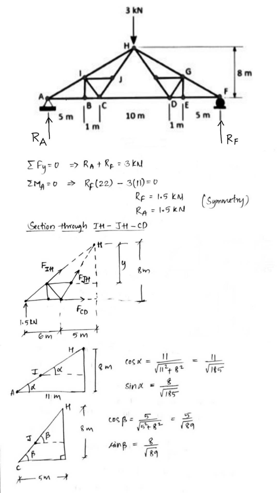
 Question 2. A truss structure is shown in Figure 2. Consider
points A and F have pin and roller supports, respectively. Use the
method of Section to determine the forces in IH, JH and CD
members.
3 KN H G 8 m J A F B C DE | 5 m ° 10 m POLE 5 m 1 m 1 m
Question 2. A truss structure is shown in Figure 2. Consider
points A and F have pin and roller supports, respectively. Use the
method of Section to determine the forces in IH, JH and CD
members.
3 KN H G 8 m J A F B C DE | 5 m ° 10 m POLE 5 m 1 m 1 m
Question 2. A truss structure is shown in Figure 2. Consider points A and F have...
 Question 2. A truss structure is shown in Figure 2. Consider points A and F have pin and roller supports, respectively. Use the method of Section to determine the forces in IH, JH and CD members. (20 marks) 3 kN G 8 m A B С | 5 m 10 m DE 5m 1 m 1 m Figure 2
Question 2. A truss structure is shown in Figure 2. Consider points A and F have...
 Question 2. A truss structure is shown in Figure 2. Consider points A and F have pin and roller supports, respectively. Use the method of Section to determine the forces in IH, JH and CD members. (20 marks) 3 kN 8 m BC IDE 5 m 10 m 5 ml 1 m 1 m Figure 2
Question 2. A truss structure is shown in Figure 2. Consider points A and F have...
 Question 2. A truss structure is shown in Figure 2. Consider points A and F have pin and roller supports, respectively. Use the method of Section to determine the forces in IH, JH and CD members. (20 marks) 3 KN 8 m IDE 5 m 10 m 5 5 m 1 m 1 m Figure 2 Sec 1 Pages: 2 of 2 Words: 81 of 177 188
1. A simple truss structure is given in iure I below, joint A is commected to...
 1. A simple truss structure is given in iure I below, joint A is commected to simple pin support and Joint G is resting on roller support. Knowing that external horizontal force of 100kN acts on joint B, and vertical forces of 150KN and 50kN are acting on joint D and respectively. Determine; (a) The reaction forces at supports A and B. (3 marks) (b) Forces carmed by members AB, AD, BC, BD, CD and CE, and indicate if the...
Q1. Consider a truss shown in Fig.1. Joint A sits on a pin support and I...
 Q1. Consider a truss shown in Fig.1. Joint A sits on a pin support and I on a roller support. () Determine the forces on members CD, FG and Hl, using two different methods (a) and (b). Identify the forces as Tension or Compression. (ii) Determine the member that carries maximum tension. (a) method of Joints, and (b) method of Sections 200 kN 200 kN 200 kN 200 kN 200 kN 4 m 3 m -5 m Fig.1 Truss
Statics problems Question A2 The plane truss shown in Figure A2 is supported at points A and J. -30° and the external loads are Fi 1.5 kN and F 3 kN. Draw the free body diagram of the truss. D...
 Statics problems
Question A2 The plane truss shown in Figure A2 is supported at points A and J. -30° and the external loads are Fi 1.5 kN and F 3 kN. Draw the free body diagram of the truss. Determine all the reactions at the supports or, if this is not possible, explain why. a) Calculate the internal forces in members CF, EH, GH and HI, stating whether they are in tension or compression. b) (12) Are members CF and...
Statics problems
Question A2 The plane truss shown in Figure A2 is supported at points A and J. -30° and the external loads are Fi 1.5 kN and F 3 kN. Draw the free body diagram of the truss. Determine all the reactions at the supports or, if this is not possible, explain why. a) Calculate the internal forces in members CF, EH, GH and HI, stating whether they are in tension or compression. b) (12) Are members CF and...
QUESTION 3 The truss shown in the Figure 3 is having hinged supports at A and B, assuming that the EA is constant for a...
 QUESTION 3 The truss shown in the Figure 3 is having hinged supports at A and B, assuming that the EA is constant for all the members. Use a flexibility method to determine the forces in each member and reactions at the supports. 80 kN 5 m 5 m 5 m 5 m Figure 3 130 marks) Total Marks [100
QUESTION 3 The truss shown in the Figure 3 is having hinged supports at A and B, assuming that the...
QUESTION 3 The truss shown in the Figure 3 is having hinged supports at A and B, assuming that the EA is constant for all the members. Use a flexibility method to determine the forces in each member and reactions at the supports. 80 kN 5 m 5 m 5 m 5 m Figure 3 130 marks) Total Marks [100
QUESTION 3 The truss shown in the Figure 3 is having hinged supports at A and B, assuming that the...
statistics, Truss structure
 for the following truss structure, determine all member forces and state whether the members are in compression or tension. there are pin and roller supports at H and A respectively
Problem No. 2 (100 points) For the Baltimore bridge truss shown below answer the following questions:...
 Problem No. 2 (100 points) For the Baltimore bridge truss shown below answer the following questions: 1) Calculate Reaction Forces (FBD is already drawn assuming a pin support at A and a roller support at I) (10) 2) What is status of the Truss (determinate or indeterminate)? (10) 3) Obtain ALL the Zero force member (30) 4) Using method of Joints, find force in member PF and PG specify if these forces are in Tension or Compression? (25) 5) Using...
 Question 2. A truss structure is shown in Figure 2. Consider
points A and F have pin and roller supports, respectively. Use the
method of Section to determine the forces in IH, JH and CD
members.
3 KN H G 8 m J A F B C DE | 5 m ° 10 m POLE 5 m 1 m 1 m
Question 2. A truss structure is shown in Figure 2. Consider
points A and F have pin and roller supports, respectively. Use the
method of Section to determine the forces in IH, JH and CD
members.
3 KN H G 8 m J A F B C DE | 5 m ° 10 m POLE 5 m 1 m 1 m
 Question 2. A truss structure is shown in Figure 2. Consider points A and F have pin and roller supports, respectively. Use the method of Section to determine the forces in IH, JH and CD members. (20 marks) 3 kN G 8 m A B С | 5 m 10 m DE 5m 1 m 1 m Figure 2
 Question 2. A truss structure is shown in Figure 2. Consider points A and F have pin and roller supports, respectively. Use the method of Section to determine the forces in IH, JH and CD members. (20 marks) 3 kN 8 m BC IDE 5 m 10 m 5 ml 1 m 1 m Figure 2
 Question 2. A truss structure is shown in Figure 2. Consider points A and F have pin and roller supports, respectively. Use the method of Section to determine the forces in IH, JH and CD members. (20 marks) 3 KN 8 m IDE 5 m 10 m 5 5 m 1 m 1 m Figure 2 Sec 1 Pages: 2 of 2 Words: 81 of 177 188
 1. A simple truss structure is given in iure I below, joint A is commected to simple pin support and Joint G is resting on roller support. Knowing that external horizontal force of 100kN acts on joint B, and vertical forces of 150KN and 50kN are acting on joint D and respectively. Determine; (a) The reaction forces at supports A and B. (3 marks) (b) Forces carmed by members AB, AD, BC, BD, CD and CE, and indicate if the...
 Q1. Consider a truss shown in Fig.1. Joint A sits on a pin support and I on a roller support. () Determine the forces on members CD, FG and Hl, using two different methods (a) and (b). Identify the forces as Tension or Compression. (ii) Determine the member that carries maximum tension. (a) method of Joints, and (b) method of Sections 200 kN 200 kN 200 kN 200 kN 200 kN 4 m 3 m -5 m Fig.1 Truss
 Statics problems
Question A2 The plane truss shown in Figure A2 is supported at points A and J. -30° and the external loads are Fi 1.5 kN and F 3 kN. Draw the free body diagram of the truss. Determine all the reactions at the supports or, if this is not possible, explain why. a) Calculate the internal forces in members CF, EH, GH and HI, stating whether they are in tension or compression. b) (12) Are members CF and...
Statics problems
Question A2 The plane truss shown in Figure A2 is supported at points A and J. -30° and the external loads are Fi 1.5 kN and F 3 kN. Draw the free body diagram of the truss. Determine all the reactions at the supports or, if this is not possible, explain why. a) Calculate the internal forces in members CF, EH, GH and HI, stating whether they are in tension or compression. b) (12) Are members CF and...
 QUESTION 3 The truss shown in the Figure 3 is having hinged supports at A and B, assuming that the EA is constant for all the members. Use a flexibility method to determine the forces in each member and reactions at the supports. 80 kN 5 m 5 m 5 m 5 m Figure 3 130 marks) Total Marks [100
QUESTION 3 The truss shown in the Figure 3 is having hinged supports at A and B, assuming that the...
QUESTION 3 The truss shown in the Figure 3 is having hinged supports at A and B, assuming that the EA is constant for all the members. Use a flexibility method to determine the forces in each member and reactions at the supports. 80 kN 5 m 5 m 5 m 5 m Figure 3 130 marks) Total Marks [100
QUESTION 3 The truss shown in the Figure 3 is having hinged supports at A and B, assuming that the...
 Problem No. 2 (100 points) For the Baltimore bridge truss shown below answer the following questions: 1) Calculate Reaction Forces (FBD is already drawn assuming a pin support at A and a roller support at I) (10) 2) What is status of the Truss (determinate or indeterminate)? (10) 3) Obtain ALL the Zero force member (30) 4) Using method of Joints, find force in member PF and PG specify if these forces are in Tension or Compression? (25) 5) Using...
Most questions answered within 3 hours.
-
The average length of time between arrivals at a turnpike
toll-booth is 26 seconds. What is...
asked 12 minutes ago -
(a) A piston at 6.1 atm contains a gas that occupies a volume of
3.5 L....
asked 1 hour ago -
Please answer true or false. Words
cannot be changed or added in to make it true...
asked 1 hour ago -
An empty test tube weighs 15.923 grams. Then,
MgCl2•6H2O is added into the test tube. After...
asked 1 hour ago -
Assume memory access is 10 units of time and disk access is
10000 units of time....
asked 1 hour ago -
1. Are all good samples random?
2. Magazines often report surveys giving statistics such as “63%...
asked 2 hours ago -
Under all the various types of market structures, firms
must eventually earn some economic profits for...
asked 1 hour ago -
Consider the following fitness regime for a single locus trait
with two co-dominant alleles: w11 =...
asked 1 hour ago -
A large cable company reports the following.
80% of its customers subscribe to its cable TV...
asked 2 hours ago -
Please answer the question in brief.
Discuss the role of ERP in organizations. Are ERP tools...
asked 1 hour ago -
Discuss the pros and cons of collaborative software such
as SameTime. Does it increase productivity? What...
asked 2 hours ago -
Buying your in-laws a gift because it’s expected is
due to the ____________ motive of gift-giving....
asked 2 hours ago