
#5 is only I need in which we need to plot it on Matlab and I don't know how to plot it.
Homework Answers
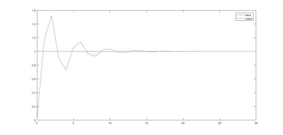
y(t) is plotted by taking Laplace Transform of differential equation and then plotting y(t) by taking inverse transform-
For step input u(t) and k=10
close all
clear all
syms s t
m =38; %mass of body
xi = 0.2; %damping ratio
k=10; %variable
T = 30; %Total time of simulation
i = 1;
wo = sqrt(k/m); %Natural frequency
G = (2*xi*wo*s+wo.^2)/(s^2+2*xi*wo*s+wo.^2);
g(t) = ilaplace(G/s,t);
t= 0:1:T;
u = ones(size(t)); %step input(all 1's for t>0)
for t= 0:1:T
y(i,1) =g(t);
i = i+1;
end
t = 0:1:T;
plot(t,u,t,y)
legend ('input','output');

As k will be increased, wo will increase and the response will become faster,
for k=100 (The value of k changed in above code)
For
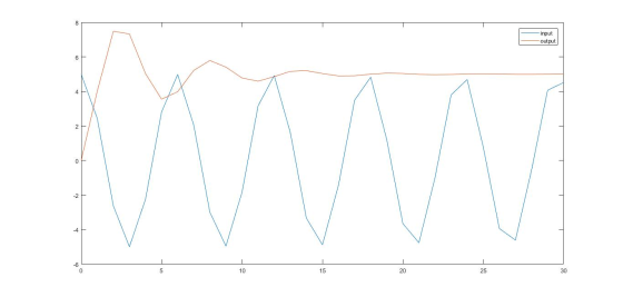
sinusoidal inputs-
Code gets modified slightly-
For k=10, input = 0.5 e^j20t (input frequency 20rad/sec)
close all
clear all
syms s t
m =38; %mass of body
xi = 0.2; %damping ratio
k=10; %variable
T = 30; %Total time of simulation
i = 1;
j = sqrt(-1);
wo = sqrt(k/m); %Natural frequency
G = (2*xi*wo*s+wo.^2)/(s^2+2*xi*wo*s+wo.^2);
g(t) = ilaplace(G/s,t);
t= 0:1:T;
for t= 0:1:T
u(i,1) = 0.5*exp(j*20*t); %Input
y(i,1) =g(t)*u(i,1);
i = i+1;
end
t = 0:1:T;
plot(t,u,t,abs(y))
legend ('input','output');
Output-

For k =100 (Response settles faster)
For k =50, input frequency = 200rad/sec
Input amplitude =5
u(i,1) = 5*exp(j*200*t);
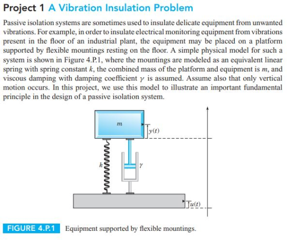
Project 1 A Vibration Insulation Problem Passive isolation systems are sometimes used to insulate delicate equipment...
 Project 1 A Vibration Insulation Problem Passive isolation systems are sometimes used to insulate delicate equipment from unwanted vibrations. For example, in order to insulate electrical monitoring equipment from vibrations present in the floor of an industrial plant, the equipment may be placed on a platform supported by flexible mountings resting on the floor. A simple physical model for such a system is shown in Figure 4.P.1, where the mountings are modeled as an equivalent linear spring with spring constant...
A vibration isolation block is to be installed in a laboratory so that the vibration from...
 A vibration isolation block is to be installed in a laboratory so that the vibration from adjacent factory operations will not disturb certain experiments. If the isolation block weighs (W) lb and the surrounding floor and foundation vibrate at (F) cycles per minute. The motion of the isolation block is limited to 10% of the floor vibration Isolation block Given: W-1380 lb f- 1730 cpm 1. Determine the natural period, natural circular frequency, and natural cyclic frequency when the 2,...
The Advanced Laser Interferometer Gravitational-wave Observatory (Advanced LIGO) experiment was recently credited with confirming the existence...
 The Advanced Laser Interferometer Gravitational-wave Observatory (Advanced LIGO) experiment was recently credited with confirming the existence of graviational waves for the first time. Key to its success was the development of a vibration isolation system to eliminate motion of lasers and mirrors. One requirement of the isolation system was to reduce seismic disturbances (base excitation) that oscillate at 0.16 Hz to produce system oscillations with a displacement transmissiblility is 1/10. The mass of the isolation mount is to be 100...
Exercises 1. (introduction) Sketch or plot the displacement of the mass in a mass-spring system for at least two per...
 Exercises 1. (introduction) Sketch or plot the displacement of the mass in a mass-spring system for at least two periods for the case when Wn-2rad/s, 괴,-1mm, and eto =-v/5mm/s. 2. (introduction) The approximation sin θ ะ θ is reasonable for θ < 10°. If a pendulum of length 0.5m, has an initial position of 0()0, what is the maximum value of the initial angular velocity that can be given to the pendulum without violating this smll angle approximation? 3. (harmonic...
فب this is an intro to mechanical ViBRATION Problem, I know the solution to this problem...
 فب
this is an intro to mechanical ViBRATION Problem, I know the
solution to this problem using matrixes, but this problems weights
6 pts out of the 100 overall course grade I want a 100% full
correction to this problem, I saw a solution on this problem on
previous post but its not full and contain errors
Consider a mass m linked to a support P by a spring of stiffness k and a viscous friction damper with coefficient a.....
فب
this is an intro to mechanical ViBRATION Problem, I know the
solution to this problem using matrixes, but this problems weights
6 pts out of the 100 overall course grade I want a 100% full
correction to this problem, I saw a solution on this problem on
previous post but its not full and contain errors
Consider a mass m linked to a support P by a spring of stiffness k and a viscous friction damper with coefficient a.....
Explain why it is necessary to conduct vibrational tests for structures Q5 (a) (5 marks) The...
 Explain why it is necessary to conduct vibrational tests for structures Q5 (a) (5 marks) The block shown in Figure Q5 has a mass m and is supported on the solid ground by a spring with stiffness k and a parallel viscous damper with damping constant d. An out of balance force F(t) is exerted on the block. Suclh force F(t) is approximated by a harmonic function causing a steady state displacement x(t) shown in Figure Q5 The following relationship...
2. then design the LF components Ri. R2,and C to produce and plot with Matlab the following step ...
 2. then design the LF components Ri. R2,and C to produce and plot with Matlab the following step responses by the PLL a. overdamped, b. underdamped, c. critically damped; 3. calculate the phase step response's following parameters: a. b. c. d. rise time T peak time Tp (if applicable) percent overshoot %OS(if applicable) settling time T, c) calculate the steady state phase error lim0e(t) for both PLL types, and draw conclusions whether your PLL can track the: i. incoming signal's...
I only need MATLAB solution with commands The damping ratio, ^, effects the performance of a...
 I only need MATLAB solution with commands
The damping ratio, ^, effects the performance of a system. Using MATLAB, for a single loop second order feedback system, find the step response of the system for values of wn 1 and = 0.1, 0.4, 0.7 , 1.0 and 2.0 E(s) R(s) G(s) Y(s) s(s +2,) Plot all the results in the same figure window and fill in the following table. Rise Time Peak Time % Overshoot Settling Time Steady State Value...
I only need MATLAB solution with commands
The damping ratio, ^, effects the performance of a system. Using MATLAB, for a single loop second order feedback system, find the step response of the system for values of wn 1 and = 0.1, 0.4, 0.7 , 1.0 and 2.0 E(s) R(s) G(s) Y(s) s(s +2,) Plot all the results in the same figure window and fill in the following table. Rise Time Peak Time % Overshoot Settling Time Steady State Value...
Show Matlab plot comparasion properly please 2) Let a system with an LTI model be 100...
 Show Matlab plot comparasion properly please
2) Let a system with an LTI model be 100 G(s) = 2s2 + 24s + 200 a) Determine the zeros, poles, the steady state step response (aka DC gain), the damping ratio, and the natural frequency b) Find the step response of the system manually and plot the y(t) signal on Matlab c) Use Simulink to simulate the same step response and compare both by taking the L2 norm of the error between...
Show Matlab plot comparasion properly please
2) Let a system with an LTI model be 100 G(s) = 2s2 + 24s + 200 a) Determine the zeros, poles, the steady state step response (aka DC gain), the damping ratio, and the natural frequency b) Find the step response of the system manually and plot the y(t) signal on Matlab c) Use Simulink to simulate the same step response and compare both by taking the L2 norm of the error between...
1: The plot shown below represents the step response of a second-order LTI system (with input...
 1: The plot shown below represents the step response of a second-order LTI system (with input (t) and output y(t)) with zero initial conditions. From the step response: (a) Estimate the peak time tp, and the maximum percentage overshoot %Mp. (b) Estimate the natural frequency wn and the damping ratio c. (c) Derive a differential equation corresponding to this system using the results of parts (a) and (b). Step Response X: 085 Y: 1.261 Amplitude 0 0.5 1 1.5 2...
 Project 1 A Vibration Insulation Problem Passive isolation systems are sometimes used to insulate delicate equipment from unwanted vibrations. For example, in order to insulate electrical monitoring equipment from vibrations present in the floor of an industrial plant, the equipment may be placed on a platform supported by flexible mountings resting on the floor. A simple physical model for such a system is shown in Figure 4.P.1, where the mountings are modeled as an equivalent linear spring with spring constant...
 A vibration isolation block is to be installed in a laboratory so that the vibration from adjacent factory operations will not disturb certain experiments. If the isolation block weighs (W) lb and the surrounding floor and foundation vibrate at (F) cycles per minute. The motion of the isolation block is limited to 10% of the floor vibration Isolation block Given: W-1380 lb f- 1730 cpm 1. Determine the natural period, natural circular frequency, and natural cyclic frequency when the 2,...
 The Advanced Laser Interferometer Gravitational-wave Observatory (Advanced LIGO) experiment was recently credited with confirming the existence of graviational waves for the first time. Key to its success was the development of a vibration isolation system to eliminate motion of lasers and mirrors. One requirement of the isolation system was to reduce seismic disturbances (base excitation) that oscillate at 0.16 Hz to produce system oscillations with a displacement transmissiblility is 1/10. The mass of the isolation mount is to be 100...
 Exercises 1. (introduction) Sketch or plot the displacement of the mass in a mass-spring system for at least two periods for the case when Wn-2rad/s, 괴,-1mm, and eto =-v/5mm/s. 2. (introduction) The approximation sin θ ะ θ is reasonable for θ < 10°. If a pendulum of length 0.5m, has an initial position of 0()0, what is the maximum value of the initial angular velocity that can be given to the pendulum without violating this smll angle approximation? 3. (harmonic...
 فب
this is an intro to mechanical ViBRATION Problem, I know the
solution to this problem using matrixes, but this problems weights
6 pts out of the 100 overall course grade I want a 100% full
correction to this problem, I saw a solution on this problem on
previous post but its not full and contain errors
Consider a mass m linked to a support P by a spring of stiffness k and a viscous friction damper with coefficient a.....
فب
this is an intro to mechanical ViBRATION Problem, I know the
solution to this problem using matrixes, but this problems weights
6 pts out of the 100 overall course grade I want a 100% full
correction to this problem, I saw a solution on this problem on
previous post but its not full and contain errors
Consider a mass m linked to a support P by a spring of stiffness k and a viscous friction damper with coefficient a.....
 Explain why it is necessary to conduct vibrational tests for structures Q5 (a) (5 marks) The block shown in Figure Q5 has a mass m and is supported on the solid ground by a spring with stiffness k and a parallel viscous damper with damping constant d. An out of balance force F(t) is exerted on the block. Suclh force F(t) is approximated by a harmonic function causing a steady state displacement x(t) shown in Figure Q5 The following relationship...
 2. then design the LF components Ri. R2,and C to produce and plot with Matlab the following step responses by the PLL a. overdamped, b. underdamped, c. critically damped; 3. calculate the phase step response's following parameters: a. b. c. d. rise time T peak time Tp (if applicable) percent overshoot %OS(if applicable) settling time T, c) calculate the steady state phase error lim0e(t) for both PLL types, and draw conclusions whether your PLL can track the: i. incoming signal's...
 I only need MATLAB solution with commands
The damping ratio, ^, effects the performance of a system. Using MATLAB, for a single loop second order feedback system, find the step response of the system for values of wn 1 and = 0.1, 0.4, 0.7 , 1.0 and 2.0 E(s) R(s) G(s) Y(s) s(s +2,) Plot all the results in the same figure window and fill in the following table. Rise Time Peak Time % Overshoot Settling Time Steady State Value...
I only need MATLAB solution with commands
The damping ratio, ^, effects the performance of a system. Using MATLAB, for a single loop second order feedback system, find the step response of the system for values of wn 1 and = 0.1, 0.4, 0.7 , 1.0 and 2.0 E(s) R(s) G(s) Y(s) s(s +2,) Plot all the results in the same figure window and fill in the following table. Rise Time Peak Time % Overshoot Settling Time Steady State Value...
 Show Matlab plot comparasion properly please
2) Let a system with an LTI model be 100 G(s) = 2s2 + 24s + 200 a) Determine the zeros, poles, the steady state step response (aka DC gain), the damping ratio, and the natural frequency b) Find the step response of the system manually and plot the y(t) signal on Matlab c) Use Simulink to simulate the same step response and compare both by taking the L2 norm of the error between...
Show Matlab plot comparasion properly please
2) Let a system with an LTI model be 100 G(s) = 2s2 + 24s + 200 a) Determine the zeros, poles, the steady state step response (aka DC gain), the damping ratio, and the natural frequency b) Find the step response of the system manually and plot the y(t) signal on Matlab c) Use Simulink to simulate the same step response and compare both by taking the L2 norm of the error between...
 1: The plot shown below represents the step response of a second-order LTI system (with input (t) and output y(t)) with zero initial conditions. From the step response: (a) Estimate the peak time tp, and the maximum percentage overshoot %Mp. (b) Estimate the natural frequency wn and the damping ratio c. (c) Derive a differential equation corresponding to this system using the results of parts (a) and (b). Step Response X: 085 Y: 1.261 Amplitude 0 0.5 1 1.5 2...
Most questions answered within 3 hours.
-
Due to a recession, expected inflation this year is only 2.25%.
However, the inflation rate in...
asked 19 seconds ago -
Write four functions: (IN PYTHON 3)
1) bound(l) - given a list of integers l, compute...
asked 2 minutes ago -
A quarterback throws a football. When the football leaves his
hand, it has a horizontal velocity...
asked 10 minutes ago -
he term "reproductive isolation mechanism" refers to
inability of a species to continue reproduction
specific areas...
asked 12 minutes ago -
In a certain binary-star system, each star has the same mass
which is 4.4 times of...
asked 17 minutes ago -
Use the model of the small open economy (Apply the small
open economy model of real...
asked 24 minutes ago -
The structure Car is declared as follows: struct Car { string
carMake; string carModel; int yearModel;...
asked 33 minutes ago -
Consider a transformer with 125 turns of wire in the primary
winding and 1475 turns of...
asked 34 minutes ago -
Let h be the depth below the surface of the ocean at which the
absolute pressure...
asked 35 minutes ago -
Apply the four-stage New Product Development model shown in page
325 of your text book
(Concept...
asked 44 minutes ago -
An enzyme catalyzes the reaction A ⇌ B. The enzyme is present at
a concentration of...
asked 52 minutes ago -
The number of years of education of self-employed individuals in
the United States has a population...
asked 1 hour ago