
Homework Answers
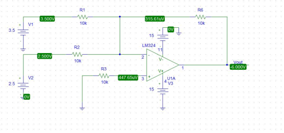
Schematic-

Expression of output voltage-
Applying KCL to inverting terminal of Op Amp-


| V1 (V) | V2 (V) | Vout (V) |
| 0.5 | 4.5 | -5 |
| 1.0 | 4.0 | -5 |
| 1.5 | 3.5 | -5 |
| -2 | -4 | 6 |
| 3.5 | 2.5 | -6 |
| 4 | 3 | -7 |
| 1.5 | 1.5 | -3 |
Schematic of some readings-
Vo=-3

Vo = -6
For Vo=-5

Add Answer to:
4.0 First Circuit. The summing junction circuit Figure 2-4 below is the circuit for summing two...
"the difference junction circuit" Figure 2-5 below is the circuit for subtracting two voltages, Vi and...
 "the difference junction circuit"
Figure 2-5 below is the circuit for subtracting two voltages, Vi and 12. Again, the required components are an op-amp and resistors. 15V V2 R3 R1 100kOhm 100kOhm - 15V -15V 15V Vout R2 100kOhm R4 w 100kOhm 15V -15V Figure 2-5: The Difference Circuit Experiment Steps 1. Build the circuit according to the circuit diagram. Notice that the two potentiometer on the left side are 0 - 1 k 2 potentiometers. Set and measure the...
"the difference junction circuit"
Figure 2-5 below is the circuit for subtracting two voltages, Vi and 12. Again, the required components are an op-amp and resistors. 15V V2 R3 R1 100kOhm 100kOhm - 15V -15V 15V Vout R2 100kOhm R4 w 100kOhm 15V -15V Figure 2-5: The Difference Circuit Experiment Steps 1. Build the circuit according to the circuit diagram. Notice that the two potentiometer on the left side are 0 - 1 k 2 potentiometers. Set and measure the...
8.) In the OP amp circuit shown in Figure 8 , determine the value of resistor...
 8.) In the OP amp circuit shown in Figure 8 , determine the
value of resistor R2 needed to establish an input trip point
voltage of 6.75 Volts ( i.e. when input signal voltage V in exceeds
6.75 V the OP amp’s output voltage changes state ) . ( 60 pts )
R2 = _______________
If the OP AMP in Figure 8 was biased by DC voltages of + / - 15
Volts , and the value of resistor R2...
8.) In the OP amp circuit shown in Figure 8 , determine the
value of resistor R2 needed to establish an input trip point
voltage of 6.75 Volts ( i.e. when input signal voltage V in exceeds
6.75 V the OP amp’s output voltage changes state ) . ( 60 pts )
R2 = _______________
If the OP AMP in Figure 8 was biased by DC voltages of + / - 15
Volts , and the value of resistor R2...
To obtain the difference between two different inputs, we can connect them to the positive and...
 To obtain the difference between two different inputs, we can connect them to the positive and negative pins of the Opamp. R1 7 +15V - opamp Ra AL15V Vout = 2 (U2-01) Where, R=R3 R2RA Figure 6: The difference amplifier The voltage follower is a non-inverting amplifier configuration with a gain of unity. Its output basically “follows” its input. The voltage follower's main virtue is that it has a very high input resistance. This is useful for driving a low...
Part C - Saturation of a summing op amp circuit For the circuit shown(Figure 2), determine...
 Part C - Saturation of a summing op amp circuit
For the circuit shown(Figure 2), determine the range (i.e.,
maximum and minimum values) of V1V1 such that the op amp operates
in the linear region. Assume that R1 = 5.0 kΩ , R2 = 8.2 kΩ , R3 =
8.2 kΩ , RF = 180 kΩ , V2 = 10 mV, V3 = 60 mV , and VCC = 15 V
.
Express your answer to three significant figures separated...
Part C - Saturation of a summing op amp circuit
For the circuit shown(Figure 2), determine the range (i.e.,
maximum and minimum values) of V1V1 such that the op amp operates
in the linear region. Assume that R1 = 5.0 kΩ , R2 = 8.2 kΩ , R3 =
8.2 kΩ , RF = 180 kΩ , V2 = 10 mV, V3 = 60 mV , and VCC = 15 V
.
Express your answer to three significant figures separated...
Use the circuit diagram as shown in Figure A below to conduct the experiment and answer...
 Use the circuit diagram as shown in Figure A below to conduct the experiment and answer the questions 1 to 6. VCC VCC 15V 15V U2 U1 + R3 + 741 Voutt Vouth 6 R1 741 1.0kΩ 2.2k VEE VEE -15V Vin= 0.75 VIP-pl @ 2 kHz -15V R2 R4 TH 4.7ΚΩ 10kΩ Figure A Question 3 3 pts Focus on Op-amp U1 ("Both op-amps have to be completely connected as shown in Figure A) • Use myDAQ's oscilloscope to...
MI Review Consider the circuits shown in (Figure 1). (Figure 2), (Figure 3), (Figure 4), (Figure...
 MI Review Consider the circuits shown in (Figure 1). (Figure 2), (Figure 3), (Figure 4), (Figure 5). Assume that the op amp is ideal. Each of the circuits has negative feedback, so the summing point constraint applies. Suppose that R1 = 6 kN and R2 = 5 kN. Part A For the circuit shown in (Figure 1) find the value of vo. Express your answer to three significant figures and include the appropriate units. v. = Value Units Figure Figure...
Use the circuit diagram as shown in Figure A below to conduct the experiment and answer...
 Use the circuit diagram as shown in Figure A below to conduct the experiment and answer the questions 1 to 6. VCC VCC 15V 15V U2 U1 + R3 + 741 Voutt Vouth 6 R1 741 1.0kΩ 2.2k VEE VEE -15V Vin= 0.75 VIP-pl @ 2 kHz -15V R2 R4 TH 4.7ΚΩ 10kΩ Figure A Question 5 3 pts Op-amp U1&U2 • Use myDAQ's oscilloscope to capture the input waveform Vin (on Channel O) and the final output waveform Vout2...
Question 8 5 pts The circuit shown in the figure below contains three resistors (R1, R2,...
 Question 8 5 pts The circuit shown in the figure below contains three resistors (R1, R2, and Rs) and three batteries (VA. Vg, and V). The resistor values are: R2-2 Ohms, R2-R3-6 Ohms, and the battery voltages are VA-25 V. V8-15V, and Vc-20 V. When the circuit is connected, what will be the power dissipated by R2? VC R 3 VA VB R2 R₃ 10W 2.0 W oooo 5.0 W 6.0 W 7.5 W Question 9 5 pts The circuit...
 "the difference junction circuit"
Figure 2-5 below is the circuit for subtracting two voltages, Vi and 12. Again, the required components are an op-amp and resistors. 15V V2 R3 R1 100kOhm 100kOhm - 15V -15V 15V Vout R2 100kOhm R4 w 100kOhm 15V -15V Figure 2-5: The Difference Circuit Experiment Steps 1. Build the circuit according to the circuit diagram. Notice that the two potentiometer on the left side are 0 - 1 k 2 potentiometers. Set and measure the...
"the difference junction circuit"
Figure 2-5 below is the circuit for subtracting two voltages, Vi and 12. Again, the required components are an op-amp and resistors. 15V V2 R3 R1 100kOhm 100kOhm - 15V -15V 15V Vout R2 100kOhm R4 w 100kOhm 15V -15V Figure 2-5: The Difference Circuit Experiment Steps 1. Build the circuit according to the circuit diagram. Notice that the two potentiometer on the left side are 0 - 1 k 2 potentiometers. Set and measure the...
 8.) In the OP amp circuit shown in Figure 8 , determine the
value of resistor R2 needed to establish an input trip point
voltage of 6.75 Volts ( i.e. when input signal voltage V in exceeds
6.75 V the OP amp’s output voltage changes state ) . ( 60 pts )
R2 = _______________
If the OP AMP in Figure 8 was biased by DC voltages of + / - 15
Volts , and the value of resistor R2...
8.) In the OP amp circuit shown in Figure 8 , determine the
value of resistor R2 needed to establish an input trip point
voltage of 6.75 Volts ( i.e. when input signal voltage V in exceeds
6.75 V the OP amp’s output voltage changes state ) . ( 60 pts )
R2 = _______________
If the OP AMP in Figure 8 was biased by DC voltages of + / - 15
Volts , and the value of resistor R2...
 To obtain the difference between two different inputs, we can connect them to the positive and negative pins of the Opamp. R1 7 +15V - opamp Ra AL15V Vout = 2 (U2-01) Where, R=R3 R2RA Figure 6: The difference amplifier The voltage follower is a non-inverting amplifier configuration with a gain of unity. Its output basically “follows” its input. The voltage follower's main virtue is that it has a very high input resistance. This is useful for driving a low...
 Part C - Saturation of a summing op amp circuit
For the circuit shown(Figure 2), determine the range (i.e.,
maximum and minimum values) of V1V1 such that the op amp operates
in the linear region. Assume that R1 = 5.0 kΩ , R2 = 8.2 kΩ , R3 =
8.2 kΩ , RF = 180 kΩ , V2 = 10 mV, V3 = 60 mV , and VCC = 15 V
.
Express your answer to three significant figures separated...
Part C - Saturation of a summing op amp circuit
For the circuit shown(Figure 2), determine the range (i.e.,
maximum and minimum values) of V1V1 such that the op amp operates
in the linear region. Assume that R1 = 5.0 kΩ , R2 = 8.2 kΩ , R3 =
8.2 kΩ , RF = 180 kΩ , V2 = 10 mV, V3 = 60 mV , and VCC = 15 V
.
Express your answer to three significant figures separated...
 Use the circuit diagram as shown in Figure A below to conduct the experiment and answer the questions 1 to 6. VCC VCC 15V 15V U2 U1 + R3 + 741 Voutt Vouth 6 R1 741 1.0kΩ 2.2k VEE VEE -15V Vin= 0.75 VIP-pl @ 2 kHz -15V R2 R4 TH 4.7ΚΩ 10kΩ Figure A Question 3 3 pts Focus on Op-amp U1 ("Both op-amps have to be completely connected as shown in Figure A) • Use myDAQ's oscilloscope to...
 MI Review Consider the circuits shown in (Figure 1). (Figure 2), (Figure 3), (Figure 4), (Figure 5). Assume that the op amp is ideal. Each of the circuits has negative feedback, so the summing point constraint applies. Suppose that R1 = 6 kN and R2 = 5 kN. Part A For the circuit shown in (Figure 1) find the value of vo. Express your answer to three significant figures and include the appropriate units. v. = Value Units Figure Figure...
 Use the circuit diagram as shown in Figure A below to conduct the experiment and answer the questions 1 to 6. VCC VCC 15V 15V U2 U1 + R3 + 741 Voutt Vouth 6 R1 741 1.0kΩ 2.2k VEE VEE -15V Vin= 0.75 VIP-pl @ 2 kHz -15V R2 R4 TH 4.7ΚΩ 10kΩ Figure A Question 5 3 pts Op-amp U1&U2 • Use myDAQ's oscilloscope to capture the input waveform Vin (on Channel O) and the final output waveform Vout2...
 Question 8 5 pts The circuit shown in the figure below contains three resistors (R1, R2, and Rs) and three batteries (VA. Vg, and V). The resistor values are: R2-2 Ohms, R2-R3-6 Ohms, and the battery voltages are VA-25 V. V8-15V, and Vc-20 V. When the circuit is connected, what will be the power dissipated by R2? VC R 3 VA VB R2 R₃ 10W 2.0 W oooo 5.0 W 6.0 W 7.5 W Question 9 5 pts The circuit...
Most questions answered within 3 hours.
-
3) What are the typical social structures in a global city?
asked 31 minutes ago -
Luther Corporation
Consolidated Balance Sheet
December 31, 2019 and 2018 (in $ millions)
Assets
2019
2018...
asked 33 minutes ago -
(Expected rate of return and risk) Carter Inc. is evaluating a
security. Calculate the investment’s expected...
asked 3 hours ago -
What specific indicators can point to lack of progress for
African Americans in American society?
asked 4 hours ago -
1-The Electrons in a beam are moving at 2.7×10⁸ m/s in an
electric field of 15000...
asked 4 hours ago -
A gas tank is a vertical cylinder. It has a radius of 1m, a
height of...
asked 4 hours ago -
Accent Software faces the following conditions. All of these
support Accent’s use of a market-penetration pricing...
asked 5 hours ago -
A mathematically inclined friend emails you the following
instructions: "Meet me in the cafeteria the first...
asked 5 hours ago -
A monopoly sells in two countries . The demand curves in the two
countries are p1...
asked 6 hours ago -
A .15kg rubber ball is bounced off a wall. Before hitting the
wall, the ball moves...
asked 7 hours ago -
A manufacturing company preparing to build a new plant is
considering three potential locations for it....
asked 7 hours ago -
B. If compound Y has approximately the same values of solubility
in toluene as compound X,...
asked 8 hours ago