Consider the circuit shown in (Figure 1) . Suppose that R = 6.0 k? . What...
Consider the circuit shown in (Figure 1) . Suppose that R = 6.0
k? . What is the time constant for the discharge of the
capacitor?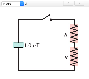
Homework Answers

Add Answer to:
Consider the circuit shown in (Figure 1) . Suppose that R = 6.0
k? . What...
Consider the circuit shown in (Figure 1) . Suppose thatR = 2.0k? . What is the...
 Consider the circuit shown in (Figure 1) . Suppose
thatR = 2.0k? .
What is the time constant for the discharge of the
capacitor?
And with this image, what is the time constant for the discharge
of the capacitor?
Consider the circuit shown in (Figure 1) . Suppose thatR = 2.0k? . What is the time constant for the discharge of the capacitor? And with this image, what is the time constant for the discharge of the capacitor?
Consider the circuit shown in (Figure 1) . Suppose
thatR = 2.0k? .
What is the time constant for the discharge of the
capacitor?
And with this image, what is the time constant for the discharge
of the capacitor?
Consider the circuit shown in (Figure 1) . Suppose thatR = 2.0k? . What is the time constant for the discharge of the capacitor? And with this image, what is the time constant for the discharge of the capacitor?
Consider the circuit shown in (Figure 1). Suppose that R = 3.0 kΩ . You may...
Consider the circuit shown in (Figure 1). Suppose that R = 3.0 kΩ . You may want to review (Pages 743 - 745) . Figure 1 of 1The circuit is shown in the figure. A 1.0- microfarad capacitor, an opened switch, and two resistors of the same resistances R are connected in series. Part A What is the time constant for the discharge of the capacitor? 1.0 uF wwww
Consider the series RC-circuit shown below for which R = 41.0 k?, C = 41.0 µF,...
 Consider the series RC-circuit shown below for which R = 41.0
k?, C = 41.0 µF, and [e m f] = 26.5 V. Find the following.
(a) the time constant of the circuit
1 s
(b) the charge on the capacitor one time constant after the switch
is closed
2 C
Consider the series RC-circuit shown below for which R = 41.0
k?, C = 41.0 µF, and [e m f] = 26.5 V. Find the following.
(a) the time constant of the circuit
1 s
(b) the charge on the capacitor one time constant after the switch
is closed
2 C
Consider the series RC-circuit shown below for which R = 64.5 k ohm, C = 35.0...
 Consider the series RC-circuit shown below for which R = 64.5 k ohm, C = 35.0 mu F, and epsilon = 13.0 V. Find the following. (a) the time constant of the circuit _____ s (b) the charge on the capacitor one time constant after the switch is closed ____ C
Consider the circuit shown in (Figure 1) , where all resistors have the same resistance R....
 Consider the circuit shown in
(Figure
1)
, where all resistors have the same resistance R.
At
t=0,
with the capacitor C
uncharged, the switch is closed.At
t=0,
the three currents can be determined by analyzing a simpler, but
equivalent, circuit. Identify this simpler circuit and use it to
find the values of
I1
,
I2,
and
I3
at
t=0.
Consider the circuit shown in (Figure 1) , where all resistors have the same resistance R. At t=0, with the...
Consider the circuit shown in
(Figure
1)
, where all resistors have the same resistance R.
At
t=0,
with the capacitor C
uncharged, the switch is closed.At
t=0,
the three currents can be determined by analyzing a simpler, but
equivalent, circuit. Identify this simpler circuit and use it to
find the values of
I1
,
I2,
and
I3
at
t=0.
Consider the circuit shown in (Figure 1) , where all resistors have the same resistance R. At t=0, with the...
9. Consider the circuit of Figure P8.9, in which R = 100 Q and R, =...
 9. Consider the circuit of Figure P8.9, in which R = 100 Q and R, = 50 12. Let v2O) - 500 mV. (a) e a = 7. Compute the equivalent resistance seen by the capacitor. Find ud for + > 0. Plot vdo for Osis St where t is the circuit time constant. b) Let a = -11. Compute the equivalent resistance seen by the capacitor. Find ud) for + > 0. Plot v) for 0 sis 21 where...
(1) Consider the RC circuit shown in Figure 1. For t<0 the switch is open, and...
 (1) Consider the RC circuit shown in Figure 1. For t<0 the switch is open, and the charge stored on the capacitor is 0. At t-0 the switch is closed, and the voltage source begins charging the capacitor. Let R1-R2-220 Ω , C-0.47 μ F , Vs-5 V. (a) Write the differential equation as an expression for the capacitor voltage fort> 0 (i.e. write the differential equation) and calculate the time constant (b) Calculate the steady-state capacitor voltage R2 R1...
5. [RC Circuits] Consider the circuit shown in Figure 5 attached. As shown, the switch is...
 5. [RC Circuits] Consider the circuit shown in Figure 5 attached. As shown, the switch is in position "A" for t < 0, and the circuit has been at rest for a long time. At time t = 0, the switch opens and the capacitor starts to drain across the resistor. (a) When the switch is closed and there is only a direct current (DC) source, the capacitor acts like an open circuit. Find the constant voltage across the capacitor...
Consider the RC circuit shown in the figure at the right. Notice that one only needs...
 Consider the RC circuit shown in the figure at the right. Notice that one only needs to move the switch from connecting to a to connecting to b in order go from charging the capacitor to discharging the capacitor. In the circuit to shown, R1-6.00 MΩ R,-9.00 Mov-27.0 V Initially the switch is left connected to b for a very long time. Answer the following five questions C=2.00 μF RI ih. y12pts.] When discharging, does the current flow through the...
ul Review Constants Consider the circuit shown in (Figure 1). Suppose that C = 16.0 nF,...
 ul Review Constants Consider the circuit shown in (Figure 1). Suppose that C = 16.0 nF, L = 26.0 mH, and R = 70.0 12. Part A For related problemsolving tips and strategies, you may want to view a Video Tutor Solution of An underdamped l- P-C series circuit. Calculate the oscillation frequency of the circuit once the capacitor has been charged and the switch has been connected to point a. Express your answer in hertz. I ALO ROO? 1...
 Consider the circuit shown in (Figure 1) . Suppose
thatR = 2.0k? .
What is the time constant for the discharge of the
capacitor?
And with this image, what is the time constant for the discharge
of the capacitor?
Consider the circuit shown in (Figure 1) . Suppose thatR = 2.0k? . What is the time constant for the discharge of the capacitor? And with this image, what is the time constant for the discharge of the capacitor?
Consider the circuit shown in (Figure 1) . Suppose
thatR = 2.0k? .
What is the time constant for the discharge of the
capacitor?
And with this image, what is the time constant for the discharge
of the capacitor?
Consider the circuit shown in (Figure 1) . Suppose thatR = 2.0k? . What is the time constant for the discharge of the capacitor? And with this image, what is the time constant for the discharge of the capacitor?
 Consider the series RC-circuit shown below for which R = 41.0
k?, C = 41.0 µF, and [e m f] = 26.5 V. Find the following.
(a) the time constant of the circuit
1 s
(b) the charge on the capacitor one time constant after the switch
is closed
2 C
Consider the series RC-circuit shown below for which R = 41.0
k?, C = 41.0 µF, and [e m f] = 26.5 V. Find the following.
(a) the time constant of the circuit
1 s
(b) the charge on the capacitor one time constant after the switch
is closed
2 C
 Consider the series RC-circuit shown below for which R = 64.5 k ohm, C = 35.0 mu F, and epsilon = 13.0 V. Find the following. (a) the time constant of the circuit _____ s (b) the charge on the capacitor one time constant after the switch is closed ____ C
 Consider the circuit shown in
(Figure
1)
, where all resistors have the same resistance R.
At
t=0,
with the capacitor C
uncharged, the switch is closed.At
t=0,
the three currents can be determined by analyzing a simpler, but
equivalent, circuit. Identify this simpler circuit and use it to
find the values of
I1
,
I2,
and
I3
at
t=0.
Consider the circuit shown in (Figure 1) , where all resistors have the same resistance R. At t=0, with the...
Consider the circuit shown in
(Figure
1)
, where all resistors have the same resistance R.
At
t=0,
with the capacitor C
uncharged, the switch is closed.At
t=0,
the three currents can be determined by analyzing a simpler, but
equivalent, circuit. Identify this simpler circuit and use it to
find the values of
I1
,
I2,
and
I3
at
t=0.
Consider the circuit shown in (Figure 1) , where all resistors have the same resistance R. At t=0, with the...
 9. Consider the circuit of Figure P8.9, in which R = 100 Q and R, = 50 12. Let v2O) - 500 mV. (a) e a = 7. Compute the equivalent resistance seen by the capacitor. Find ud for + > 0. Plot vdo for Osis St where t is the circuit time constant. b) Let a = -11. Compute the equivalent resistance seen by the capacitor. Find ud) for + > 0. Plot v) for 0 sis 21 where...
 (1) Consider the RC circuit shown in Figure 1. For t<0 the switch is open, and the charge stored on the capacitor is 0. At t-0 the switch is closed, and the voltage source begins charging the capacitor. Let R1-R2-220 Ω , C-0.47 μ F , Vs-5 V. (a) Write the differential equation as an expression for the capacitor voltage fort> 0 (i.e. write the differential equation) and calculate the time constant (b) Calculate the steady-state capacitor voltage R2 R1...
 5. [RC Circuits] Consider the circuit shown in Figure 5 attached. As shown, the switch is in position "A" for t < 0, and the circuit has been at rest for a long time. At time t = 0, the switch opens and the capacitor starts to drain across the resistor. (a) When the switch is closed and there is only a direct current (DC) source, the capacitor acts like an open circuit. Find the constant voltage across the capacitor...
 Consider the RC circuit shown in the figure at the right. Notice that one only needs to move the switch from connecting to a to connecting to b in order go from charging the capacitor to discharging the capacitor. In the circuit to shown, R1-6.00 MΩ R,-9.00 Mov-27.0 V Initially the switch is left connected to b for a very long time. Answer the following five questions C=2.00 μF RI ih. y12pts.] When discharging, does the current flow through the...
 ul Review Constants Consider the circuit shown in (Figure 1). Suppose that C = 16.0 nF, L = 26.0 mH, and R = 70.0 12. Part A For related problemsolving tips and strategies, you may want to view a Video Tutor Solution of An underdamped l- P-C series circuit. Calculate the oscillation frequency of the circuit once the capacitor has been charged and the switch has been connected to point a. Express your answer in hertz. I ALO ROO? 1...
Most questions answered within 3 hours.
-
Other decisions about scientific claims can have a much broader
impact.ENERGYarrow-10x10.png, environment, health, security - all...
asked 1 minute ago -
I need to write a research paper and work cited about this
topic: The United States...
asked 23 minutes ago -
Hello! I was wondering if I could have some help?
If the vapor pressure of carvone...
asked 46 minutes ago -
An economist wants to estimate the mean per capita income (in
thousands of dollars) for a...
asked 1 hour ago -
What would be the input/output characteristic of a circuit
obtained by putting two of your 2's-complementers...
asked 1 hour ago -
In Drosophila, the transition from the syncytial blastoderm
stage to the cellular blastoderm stage is a...
asked 1 hour ago -
Project management question:
Name 3 different types of resources (hint: humans are one
type)
asked 1 hour ago -
Consider the following reaction: C 2H 2( g) + 2H 2( g) C 2H 6(
g)...
asked 1 hour ago -
Consider a 1.0 L buffer containing 0.092 mol L-1 HCOOH and 0.100
mol L-1 HCOO-. What...
asked 2 hours ago -
Koch Realty has owned a vacant land with a FMV of
$775,000 and an adjusted basis...
asked 2 hours ago -
It is estimated 29% of all adults in United States invest in
stocks and that 85%...
asked 2 hours ago -
What does a 2-sided p value of 0.04 mean? (I am not asking if it
is...
asked 2 hours ago