
Homework Answers
![so that ****{*8 = +[[_regou a fost solar] 902 3 (27) J ditt QOT -- + ) 40 **| -3065424-1) --of-estart court)] 90 = * [-306--)](http://img.homeworklib.com/questions/0cbe1040-2903-11eb-ac78-1f186a671e6e.png?x-oss-process=image/resize,w_560)


Add Answer to:
Part A (C) using the form For the periodic functions shown in the (Figure 1) derive...
b) A periodic voltage vs(t) is applied to a RLC circuit shown in Figure 1 (b)...
 b) A periodic voltage vs(t) is applied to a RLC circuit shown in Figure 1 (b) with R=10012, L=100mH and C=1pF. The first four nonzero terms in the Fourier series is given by the following: v:(t) = 10 +2 sin(10’t)-1sin(2x10't)+sin(3x10°r) v Find the first four nonzero terms in the Fourier series of the steady-state current iſt). (20 marks) R M v.(t) Tv.(t) Figure 2(b): Circuit for Question 2
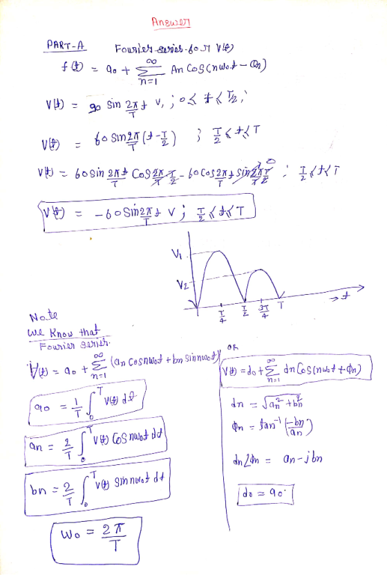
16.2 Find the Fourier series expressions for the periodic voltage functions shown in Fig. P16.2. ...
 16.2 Find the Fourier series expressions for the periodic voltage functions shown in Fig. P16.2. Note that Fig. P16.2(a) illustrates the square wave; Fig. P16.2(b) illustrates the full-wave rectified sine wave, where u(t)-Yn sin(π/T), 0 t s T; and Fig. P16.2(c) illustrates the half-wave rectified sine wave, where Figure P16.2 v(t) 2T 3T rt v(0) 2T 3T v(t) nt T/2 T 3T/2
16.2 Find the Fourier series expressions for the periodic voltage functions shown in Fig. P16.2. Note that Fig....
16.2 Find the Fourier series expressions for the periodic voltage functions shown in Fig. P16.2. Note that Fig. P16.2(a) illustrates the square wave; Fig. P16.2(b) illustrates the full-wave rectified sine wave, where u(t)-Yn sin(π/T), 0 t s T; and Fig. P16.2(c) illustrates the half-wave rectified sine wave, where Figure P16.2 v(t) 2T 3T rt v(0) 2T 3T v(t) nt T/2 T 3T/2
16.2 Find the Fourier series expressions for the periodic voltage functions shown in Fig. P16.2. Note that Fig....
6.3 Exercises In Exercises 1-5 find the current in the RLC circuit, assuming that E(t) =...
 6.3 Exercises In Exercises 1-5 find the current in the RLC circuit, assuming that E(t) = 0 fort > 0. 1. R = 3 ohms; L = 1 henrysC = .01 farads; Q. = 0 coulombs, 10 = 2 amperes. 11. Show that if E(t) = U coswt +V sin wt where U and V are constants then the steady state current in the RLC circuit shown in Figure 6.3.1 is w?RE(t) + (1/C - Lw?) E' (t) I where...
40 240 mH 1.0) 2.5 mF Part A Find the steady-state expression for io(t) in the...
 40 240 mH 1.0) 2.5 mF Part A Find the steady-state expression for io(t) in the circuit in (Figure 1) if U, = 150 sin 50t mV. Suppose that i(t) = Io cos(wt + º), where -180º < < 180°. Determine the values Io, w, . Express your answers using three significant figures separated by commas. Express Io in milliamperes, w in radians per second, o in degrees. V AJ vec O O ? 10, w, o = mA, rad/s,...
Consider the series RLC bandpass filter shown in (Figure 1). The filter has a quality of...
 Consider the series RLC bandpass filter shown in (Figure 1). The filter has a quality of 2 and a center frequency of 8 kHz. The input to the filter is vi (t) = 23 cos wt V. Suppose that C = 5 nF. Figure < 1 of 1 + VLC с L HE + + Vi R} R V. Part E Find the voltage drop across the series combination of the inductor and capacitor when w=10w, Suppose that vlc (t)...
Problem 3 The periodic voltage source in the circuit shown in Figure P3 (a) has the waveform shown in Figure P3 (b). a) Derive the expression for Cn b) Find the values of the complex coefficients Co,...
 Problem 3 The periodic voltage source in the circuit shown in Figure P3 (a) has the waveform shown in Figure P3 (b). a) Derive the expression for Cn b) Find the values of the complex coefficients Co, C1, C1, C 2, C2, C3, C3, C4, and C4 for the input voltage vg, if V,-54 V and T-10π us c) Repeat b) for Vo. d) Use the complex coefficients found in c) to estimate the average power delivered to the 250...
Use the node-voltage method to find the steady-state expression for vo(t) in the circuit in (Figure...
 Use the node-voltage method to find the steady-state expression
for vo(t) in the circuit in (Figure 1) if
vg1= 19 sin(400t+143.13∘)V,
vg2= 18.03cos(400t+33.69∘)V.
Write the steady-state expression for vo(t) as vo=Vocos(ωt+ϕ),
where −180∘<ϕ≤180∘.
EE 211/EE 212 FA19 Circuits Analysis for Engineers KEE 211/212 HW #10 -- Impedances, Sinusoidal Steady State Analysis Problem 9.57 PSpicelMultisim Use the node-voltage method to find the steady-state expression for (t) in the circuit in (Figure 1) if gl19 sin(400t143.13°) V. g218.03 cos(400t 33.69o) V. Write...
Use the node-voltage method to find the steady-state expression
for vo(t) in the circuit in (Figure 1) if
vg1= 19 sin(400t+143.13∘)V,
vg2= 18.03cos(400t+33.69∘)V.
Write the steady-state expression for vo(t) as vo=Vocos(ωt+ϕ),
where −180∘<ϕ≤180∘.
EE 211/EE 212 FA19 Circuits Analysis for Engineers KEE 211/212 HW #10 -- Impedances, Sinusoidal Steady State Analysis Problem 9.57 PSpicelMultisim Use the node-voltage method to find the steady-state expression for (t) in the circuit in (Figure 1) if gl19 sin(400t143.13°) V. g218.03 cos(400t 33.69o) V. Write...
I need help analyzing B and completing C. 1. Suppose a particle with mass m is...
 I need help analyzing B and completing C.
1. Suppose a particle with mass m is in motion in a 1D force-field depend- ing on time only, F- F(t). Determine velocity v(t) and displacement r(t) and analyze the behavior of the particle as t 0 and t ->o0 (A) F(t) eat, t 0, 0, u(0) 0; (B) F(t) = sin(wt), and F(t) cos(wt), t,w 〉 0, x(0) u(0) = 0; (C) F(t)--t , t to, β 0, x(to) 0, u(to)...
I need help analyzing B and completing C.
1. Suppose a particle with mass m is in motion in a 1D force-field depend- ing on time only, F- F(t). Determine velocity v(t) and displacement r(t) and analyze the behavior of the particle as t 0 and t ->o0 (A) F(t) eat, t 0, 0, u(0) 0; (B) F(t) = sin(wt), and F(t) cos(wt), t,w 〉 0, x(0) u(0) = 0; (C) F(t)--t , t to, β 0, x(to) 0, u(to)...
Problem 1: (25 points) Фи Figure 1 For the circuit shown in Figure 1, answer the...
 Problem 1: (25 points) Фи Figure 1 For the circuit shown in Figure 1, answer the following questions: Suppose v, (t) 340 sin wt v at 60 Hz frequency, Id-15A (Constant) A. Assuming Ls-0, when α-45°, calculate Va',1, and Pdc. (5 points) B. Assuming L 0, when a 60°, calculate Va and draw the waveforms of v,i, and vd C. Assuming L,-1mH, when α 45°, calculate V, Pdc, and the commutation/overlap D. According to Part G, draw the waveforms of...
Part C Find the numerical value of φ Express your answer using three significant figures. vec...
 Part C Find the numerical value of φ Express your answer using three significant figures. vec Submit Request Answer Problem 9.56 PSpiceMultisim Use the node voltage method to find the steady-state expression for 2 in the circuit seen in (Figure 1) if i6 cos 2500t A and Part A Find the numerical value of lo 18 cos(2500t90°) V Write the steady-state expression for io (t) as 20-10 cos(wt + φ), where _ 180° < φ Express your answer to three...
 b) A periodic voltage vs(t) is applied to a RLC circuit shown in Figure 1 (b) with R=10012, L=100mH and C=1pF. The first four nonzero terms in the Fourier series is given by the following: v:(t) = 10 +2 sin(10’t)-1sin(2x10't)+sin(3x10°r) v Find the first four nonzero terms in the Fourier series of the steady-state current iſt). (20 marks) R M v.(t) Tv.(t) Figure 2(b): Circuit for Question 2
 16.2 Find the Fourier series expressions for the periodic voltage functions shown in Fig. P16.2. Note that Fig. P16.2(a) illustrates the square wave; Fig. P16.2(b) illustrates the full-wave rectified sine wave, where u(t)-Yn sin(π/T), 0 t s T; and Fig. P16.2(c) illustrates the half-wave rectified sine wave, where Figure P16.2 v(t) 2T 3T rt v(0) 2T 3T v(t) nt T/2 T 3T/2
16.2 Find the Fourier series expressions for the periodic voltage functions shown in Fig. P16.2. Note that Fig....
16.2 Find the Fourier series expressions for the periodic voltage functions shown in Fig. P16.2. Note that Fig. P16.2(a) illustrates the square wave; Fig. P16.2(b) illustrates the full-wave rectified sine wave, where u(t)-Yn sin(π/T), 0 t s T; and Fig. P16.2(c) illustrates the half-wave rectified sine wave, where Figure P16.2 v(t) 2T 3T rt v(0) 2T 3T v(t) nt T/2 T 3T/2
16.2 Find the Fourier series expressions for the periodic voltage functions shown in Fig. P16.2. Note that Fig....
 6.3 Exercises In Exercises 1-5 find the current in the RLC circuit, assuming that E(t) = 0 fort > 0. 1. R = 3 ohms; L = 1 henrysC = .01 farads; Q. = 0 coulombs, 10 = 2 amperes. 11. Show that if E(t) = U coswt +V sin wt where U and V are constants then the steady state current in the RLC circuit shown in Figure 6.3.1 is w?RE(t) + (1/C - Lw?) E' (t) I where...
 40 240 mH 1.0) 2.5 mF Part A Find the steady-state expression for io(t) in the circuit in (Figure 1) if U, = 150 sin 50t mV. Suppose that i(t) = Io cos(wt + º), where -180º < < 180°. Determine the values Io, w, . Express your answers using three significant figures separated by commas. Express Io in milliamperes, w in radians per second, o in degrees. V AJ vec O O ? 10, w, o = mA, rad/s,...
 Consider the series RLC bandpass filter shown in (Figure 1). The filter has a quality of 2 and a center frequency of 8 kHz. The input to the filter is vi (t) = 23 cos wt V. Suppose that C = 5 nF. Figure < 1 of 1 + VLC с L HE + + Vi R} R V. Part E Find the voltage drop across the series combination of the inductor and capacitor when w=10w, Suppose that vlc (t)...
 Problem 3 The periodic voltage source in the circuit shown in Figure P3 (a) has the waveform shown in Figure P3 (b). a) Derive the expression for Cn b) Find the values of the complex coefficients Co, C1, C1, C 2, C2, C3, C3, C4, and C4 for the input voltage vg, if V,-54 V and T-10π us c) Repeat b) for Vo. d) Use the complex coefficients found in c) to estimate the average power delivered to the 250...
 Use the node-voltage method to find the steady-state expression
for vo(t) in the circuit in (Figure 1) if
vg1= 19 sin(400t+143.13∘)V,
vg2= 18.03cos(400t+33.69∘)V.
Write the steady-state expression for vo(t) as vo=Vocos(ωt+ϕ),
where −180∘<ϕ≤180∘.
EE 211/EE 212 FA19 Circuits Analysis for Engineers KEE 211/212 HW #10 -- Impedances, Sinusoidal Steady State Analysis Problem 9.57 PSpicelMultisim Use the node-voltage method to find the steady-state expression for (t) in the circuit in (Figure 1) if gl19 sin(400t143.13°) V. g218.03 cos(400t 33.69o) V. Write...
Use the node-voltage method to find the steady-state expression
for vo(t) in the circuit in (Figure 1) if
vg1= 19 sin(400t+143.13∘)V,
vg2= 18.03cos(400t+33.69∘)V.
Write the steady-state expression for vo(t) as vo=Vocos(ωt+ϕ),
where −180∘<ϕ≤180∘.
EE 211/EE 212 FA19 Circuits Analysis for Engineers KEE 211/212 HW #10 -- Impedances, Sinusoidal Steady State Analysis Problem 9.57 PSpicelMultisim Use the node-voltage method to find the steady-state expression for (t) in the circuit in (Figure 1) if gl19 sin(400t143.13°) V. g218.03 cos(400t 33.69o) V. Write...
 I need help analyzing B and completing C.
1. Suppose a particle with mass m is in motion in a 1D force-field depend- ing on time only, F- F(t). Determine velocity v(t) and displacement r(t) and analyze the behavior of the particle as t 0 and t ->o0 (A) F(t) eat, t 0, 0, u(0) 0; (B) F(t) = sin(wt), and F(t) cos(wt), t,w 〉 0, x(0) u(0) = 0; (C) F(t)--t , t to, β 0, x(to) 0, u(to)...
I need help analyzing B and completing C.
1. Suppose a particle with mass m is in motion in a 1D force-field depend- ing on time only, F- F(t). Determine velocity v(t) and displacement r(t) and analyze the behavior of the particle as t 0 and t ->o0 (A) F(t) eat, t 0, 0, u(0) 0; (B) F(t) = sin(wt), and F(t) cos(wt), t,w 〉 0, x(0) u(0) = 0; (C) F(t)--t , t to, β 0, x(to) 0, u(to)...
 Problem 1: (25 points) Фи Figure 1 For the circuit shown in Figure 1, answer the following questions: Suppose v, (t) 340 sin wt v at 60 Hz frequency, Id-15A (Constant) A. Assuming Ls-0, when α-45°, calculate Va',1, and Pdc. (5 points) B. Assuming L 0, when a 60°, calculate Va and draw the waveforms of v,i, and vd C. Assuming L,-1mH, when α 45°, calculate V, Pdc, and the commutation/overlap D. According to Part G, draw the waveforms of...
 Part C Find the numerical value of φ Express your answer using three significant figures. vec Submit Request Answer Problem 9.56 PSpiceMultisim Use the node voltage method to find the steady-state expression for 2 in the circuit seen in (Figure 1) if i6 cos 2500t A and Part A Find the numerical value of lo 18 cos(2500t90°) V Write the steady-state expression for io (t) as 20-10 cos(wt + φ), where _ 180° < φ Express your answer to three...
Most questions answered within 3 hours.
-
Design a class for python named PersonData with the following
member variables:
lastName
firstName
address
city...
asked 4 minutes ago -
How does use of the risk/need/responsivity model impact
effective rehabilitation services?
asked 8 minutes ago -
Your rich uncle has just given you a high school graduation
present of $900,000. The present,...
asked 10 minutes ago -
1=Write a program in C to get 16-bit data from Port-D and send
it to ports...
asked 9 minutes ago -
Calculate Ecell for the following reaction and conditions: 0.50
M Br2 (aq), 0.10 M Pb+2 (aq),...
asked 29 minutes ago -
There can be more than one correct answer.
Hypophysiotropic hormones:
A. released by the hypothalamus
B....
asked 35 minutes ago -
Scott Ruskin is the CEO of Decatur Materials. The company has
been struggling for the last...
asked 33 minutes ago -
If you were conducting a study involving twins regarding
genetics and/or upbringing, which would you use?...
asked 55 minutes ago -
Part 1- Inventory: You own a toy company and
you are producing wooden rocking horses. Assume...
asked 1 hour ago -
What is aromaticity?
Identify aromatic molecules, especially those containing O, N,
S and B
asked 1 hour ago -
A rubber solid circular wheel of uniform density spins about it
axis at rate of 60...
asked 1 hour ago -
DNA evidence from an early human skeleton in Britain, shows that
early inhabitants of were blue...
asked 1 hour ago