
Homework Answers
Add Answer to:
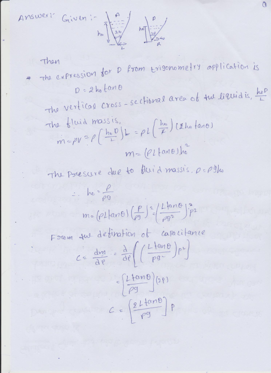
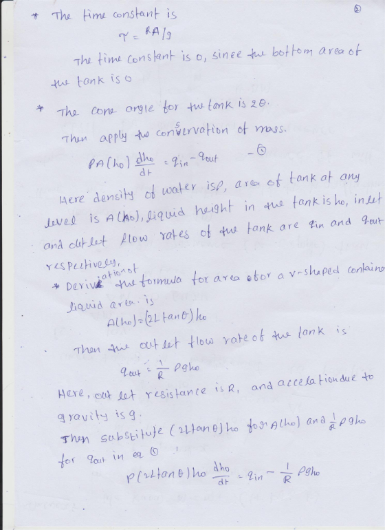
1) Consider the tank shown below. Assume that the average operating level is h a. Derive...
1 Consider the tank shown below. Assume that the average operating level is denoted by H.The resi...
 1 Consider the tank shown below. Assume that the average operating level is denoted by H.The resistance R is linear. The tank has three vertical walls and one that includes a segment with a slope. The distance separating the walls is 2m, also B-2m; and D-1.2m. The bottom of the tank is a square. a. Derive the capacitance of the container. b. Derive the time constant of the system. c. Find the transfer function that related the height in the...
6. Consider the liquid-level system shown. Assume that the outflow rate Q(m/s) through the outflow valve...
 6. Consider the liquid-level system shown. Assume that the outflow rate Q(m/s) through the outflow valve is related to the head H by: Q=kVH = 0.01VH Also assume when the inflow rate Qi is 0.015m3/s the head is constant. At t=0 the inflow valve is closed, so there is no flow for t0. Find the time necessary to empty the tank to half the original head. The area of the tank is 2m2 TIL Capacitance c
For the mechanical system shown below find the input-output equation relating xolt) to the displacement input...
 For the mechanical system shown below find the input-output equation relating xolt) to the displacement input x(t) 1. ド ド Ki Derive the transfer function X,G)/X, (s)of the mechanical system shown below. The displacements x, and xo are measured from their respective equilibrium potions. Is the system a first-order system if so, what is the time constant? 2. k1 bz k2 3. Consider the mechanical system shown below. The system is initially at rest. The displacements x, and x2 are...
(30pts) Consider the liquid level system shown in the figure. Assume the outflow rate Q (m3/s) th...
 (30pts) Consider the liquid level system shown in the figure. Assume the outflow rate Q (m3/s) through the outflow value is related to the liquid level H by Assume also that, when the inflow rate Qi and outflow rate QOare at Q = 0015m3/s, the liquid level stays at constant H. The capacitance C of the tank is 2m2 Find the steady state value of the liquid level system H. Develop the governing equations for the liquid level system and...
The figure for 4-52 is the image below. Solve problem B-4-10. Then answer the following: 1. If the head h is the input...
 The figure for 4-52 is the image below.
Solve problem B-4-10. Then answer the following: 1. If the head h is the input to the hydraulic controller and the output from the controller is y, derive the transfer function of the controller? 2. What is the control action of this controller? Screen Shot 2019-06-03 at 10.49.13 PM Q Search B-4-10. Consider the liquid-level control Figure 4-52. The inlet valve is controlled by a hydraulic integral controller. Assume that the steady-state...
The figure for 4-52 is the image below.
Solve problem B-4-10. Then answer the following: 1. If the head h is the input to the hydraulic controller and the output from the controller is y, derive the transfer function of the controller? 2. What is the control action of this controller? Screen Shot 2019-06-03 at 10.49.13 PM Q Search B-4-10. Consider the liquid-level control Figure 4-52. The inlet valve is controlled by a hydraulic integral controller. Assume that the steady-state...
Consider the liquid level system shown in Figure 1. At steady state, the inflow rate and...
 Consider the liquid level system shown in Figure 1. At steady state, the inflow rate and outflow rate are both Ở and the flow rate between the tanks is zero. The heads at tank 1 and tank 2 are both H. At t = 0, the inflow rate is changed from 0 to + , where is the small change in the inflow rate. The resulting changes in the heads (h/ and h2) and flow rates are assumed to be...
liquid-level
 Liquid Level System Consider the liquid level system shown below. At steady state, the inflow rate is Q and the outflow rate is also Q Assume that at t = 0 the inflow rate is changed from Q to Q + qr where q, is a small quantity. The disturbance input is qd, which is also a small quantity. Draw a block diagram of the system and simplify it to obtain H 2(s) as a function of Q(s) and Q...
5. (10 points) Consider the liquid-level system shown. At steady state, the inflow rate is Q:...
 5. (10 points) Consider the liquid-level system shown. At steady state, the inflow rate is Q: the outflow rates are Q1 and Q, respectively; the flow rate from tank 1 to tank 2 is Q12, and the heads of tanks 1 and 2 are H and H2, respectively. If the inflow rate is changed from Q to Q+q, determine the transfer function Hz(8)/Q(s). Assume the deviations 4,91,92,912, h, and hy are all small. 6th Jan Hathe +7 т/ н+А, JE>,+8....
1. Consider a single tank for flow rate control and water level regulation. A single tank...
 1. Consider a single tank for flow rate control and water level regulation. A single tank subject to the pump dynamics can be modeled as follows Tank dynamics: h.-le,-4M h, -e-eyh.), Pump dynamics: Q,-1(av,-0) Pump dynamics: Q,--(av,-Q.) Tank dynamics: where the parameters are defined as follows: h :water level c: valve resistance r: time constant S,: water tank area Q,: supplied flow rate a: voltage scaling factor ,: applied control input voltage (all the coefficients are positive) (A). Please apply...
Q1. Determine the solution of x(t). 4x + 20% +36x = 0 Where x(0) = 2...
 Q1. Determine the solution of x(t). 4x + 20% +36x = 0 Where x(0) = 2 m, 8(0) = 1 m/s Q1. Mass M is lifted by a pulley system as shown in Figure 1. The pulley is rotating in a clockwise direction. Assuming zero initial conditions, obtain transfer function of the system, X(s)/Ta(s). Τα S B X м k Figure 1 Consider the liquid level system shown in Figure 1. At steady state, the inflow rate and outflow rate...
 1 Consider the tank shown below. Assume that the average operating level is denoted by H.The resistance R is linear. The tank has three vertical walls and one that includes a segment with a slope. The distance separating the walls is 2m, also B-2m; and D-1.2m. The bottom of the tank is a square. a. Derive the capacitance of the container. b. Derive the time constant of the system. c. Find the transfer function that related the height in the...
 6. Consider the liquid-level system shown. Assume that the outflow rate Q(m/s) through the outflow valve is related to the head H by: Q=kVH = 0.01VH Also assume when the inflow rate Qi is 0.015m3/s the head is constant. At t=0 the inflow valve is closed, so there is no flow for t0. Find the time necessary to empty the tank to half the original head. The area of the tank is 2m2 TIL Capacitance c
 For the mechanical system shown below find the input-output equation relating xolt) to the displacement input x(t) 1. ド ド Ki Derive the transfer function X,G)/X, (s)of the mechanical system shown below. The displacements x, and xo are measured from their respective equilibrium potions. Is the system a first-order system if so, what is the time constant? 2. k1 bz k2 3. Consider the mechanical system shown below. The system is initially at rest. The displacements x, and x2 are...
 (30pts) Consider the liquid level system shown in the figure. Assume the outflow rate Q (m3/s) through the outflow value is related to the liquid level H by Assume also that, when the inflow rate Qi and outflow rate QOare at Q = 0015m3/s, the liquid level stays at constant H. The capacitance C of the tank is 2m2 Find the steady state value of the liquid level system H. Develop the governing equations for the liquid level system and...
 The figure for 4-52 is the image below.
Solve problem B-4-10. Then answer the following: 1. If the head h is the input to the hydraulic controller and the output from the controller is y, derive the transfer function of the controller? 2. What is the control action of this controller? Screen Shot 2019-06-03 at 10.49.13 PM Q Search B-4-10. Consider the liquid-level control Figure 4-52. The inlet valve is controlled by a hydraulic integral controller. Assume that the steady-state...
The figure for 4-52 is the image below.
Solve problem B-4-10. Then answer the following: 1. If the head h is the input to the hydraulic controller and the output from the controller is y, derive the transfer function of the controller? 2. What is the control action of this controller? Screen Shot 2019-06-03 at 10.49.13 PM Q Search B-4-10. Consider the liquid-level control Figure 4-52. The inlet valve is controlled by a hydraulic integral controller. Assume that the steady-state...
 Consider the liquid level system shown in Figure 1. At steady state, the inflow rate and outflow rate are both Ở and the flow rate between the tanks is zero. The heads at tank 1 and tank 2 are both H. At t = 0, the inflow rate is changed from 0 to + , where is the small change in the inflow rate. The resulting changes in the heads (h/ and h2) and flow rates are assumed to be...
 Liquid Level System Consider the liquid level system shown below. At steady state, the inflow rate is Q and the outflow rate is also Q Assume that at t = 0 the inflow rate is changed from Q to Q + qr where q, is a small quantity. The disturbance input is qd, which is also a small quantity. Draw a block diagram of the system and simplify it to obtain H 2(s) as a function of Q(s) and Q...
 5. (10 points) Consider the liquid-level system shown. At steady state, the inflow rate is Q: the outflow rates are Q1 and Q, respectively; the flow rate from tank 1 to tank 2 is Q12, and the heads of tanks 1 and 2 are H and H2, respectively. If the inflow rate is changed from Q to Q+q, determine the transfer function Hz(8)/Q(s). Assume the deviations 4,91,92,912, h, and hy are all small. 6th Jan Hathe +7 т/ н+А, JE>,+8....
 1. Consider a single tank for flow rate control and water level regulation. A single tank subject to the pump dynamics can be modeled as follows Tank dynamics: h.-le,-4M h, -e-eyh.), Pump dynamics: Q,-1(av,-0) Pump dynamics: Q,--(av,-Q.) Tank dynamics: where the parameters are defined as follows: h :water level c: valve resistance r: time constant S,: water tank area Q,: supplied flow rate a: voltage scaling factor ,: applied control input voltage (all the coefficients are positive) (A). Please apply...
 Q1. Determine the solution of x(t). 4x + 20% +36x = 0 Where x(0) = 2 m, 8(0) = 1 m/s Q1. Mass M is lifted by a pulley system as shown in Figure 1. The pulley is rotating in a clockwise direction. Assuming zero initial conditions, obtain transfer function of the system, X(s)/Ta(s). Τα S B X м k Figure 1 Consider the liquid level system shown in Figure 1. At steady state, the inflow rate and outflow rate...
Most questions answered within 3 hours.
-
Bernie's Beverages purchased some fixed assets classified as
5-year property for MACRS. The assets cost $28,000....
asked 2 minutes ago -
How many ATPs are produced from the catabolism of a 10-C
molecule of fatty acid under...
asked 6 minutes ago -
Before practicing a routine on the rings, a 64.8 kg gymnast
hangs motionless, with one hand...
asked 8 minutes ago -
If the K b of a weak base is 6.3 × 10 − 6 , what...
asked 14 minutes ago -
Which of the following is the minimum amount of moles of NaOH
that must be added...
asked 18 minutes ago -
Stories about organizational ________ provide important clues
about cultural values and norms.
a. myths
b. heroes...
asked 20 minutes ago -
Explain the criteria used in selecting a target market
BUS220 Retail Management, thank you!
asked 21 minutes ago -
Convert/Calculate the following:
Determine the identity of an elemental gas if 4.55 L weighing
35.4g, under...
asked 25 minutes ago -
Consider the equilibrium C(s)+ CO2(g) ⇌2 CO(g)
A 2.0 L flask contains a mixture of 0.10...
asked 23 minutes ago -
MATLAB
Part 1 – randFloatValue.m This function accepts two numbers,
lower and upper, and returns a...
asked 29 minutes ago -
You have been asked to hide prizes around your house for your
3-year old nephew. His...
asked 31 minutes ago -
Ammonia will decompose into nitrogen and hydrogen at high
temperature. An industrial chemist studying this reaction...
asked 37 minutes ago