
Homework Answers
Only the forces in member CB will count towards horizontal deflection at C as the virtual forces in other members is zero


Real force in member CB = N = 12.5 kN = 12500 N
Virtual force in member CB = n = 1 N

Therefore horizontal deflection at C is given as
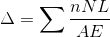
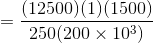
= 0.375 mm
Hence option 'd' is correct
Add Answer to:
III P Flag question Select the correct answer of horizontal deflection (mm) for joint C by...
Problem #4: Determine the horizontal deflection at joint C of the frame shown in the Figure inclu...
 A=1200mm2
Problem #4: Determine the horizontal deflection at joint C of the frame shown in the Figure including the effect of axial deformations, by the virtual work method. El- constant, E 70 GPa, l = 554(106) mmt (25 Points) 10 m 15 kN/m -75 kN- 6 m BHinge 6 m
Problem #4: Determine the horizontal deflection at joint C of the frame shown in the Figure including the effect of axial deformations, by the virtual work method. El- constant, E...
A=1200mm2
Problem #4: Determine the horizontal deflection at joint C of the frame shown in the Figure including the effect of axial deformations, by the virtual work method. El- constant, E 70 GPa, l = 554(106) mmt (25 Points) 10 m 15 kN/m -75 kN- 6 m BHinge 6 m
Problem #4: Determine the horizontal deflection at joint C of the frame shown in the Figure including the effect of axial deformations, by the virtual work method. El- constant, E...
solve for horizontal deflection at point c using virtual work, please show work for reactions and...
 solve for horizontal deflection at point c using
virtual work, please show work for reactions and all other
steps
Deflections of Trusses, Beams, and Frames: Work-Energy Methods 30 kN/m 50 KN + B T Hinge 4.5 m E=200 GPa I = 400(106)mm = 225 cm -3 m -3 m $ 4 27 & 7 9 B 3
solve for horizontal deflection at point c using
virtual work, please show work for reactions and all other
steps
Deflections of Trusses, Beams, and Frames: Work-Energy Methods 30 kN/m 50 KN + B T Hinge 4.5 m E=200 GPa I = 400(106)mm = 225 cm -3 m -3 m $ 4 27 & 7 9 B 3
Question 3 (30 points): Determine the smallest moment of inertia I required for the members of the frame shown, so that the horizontal deflection at joint C does not exceed 1 inch. Use the virtual...
 Question 3 (30 points): Determine the smallest moment of inertia I required for the members of the frame shown, so that the horizontal deflection at joint C does not exceed 1 inch. Use the virtual work method. E 29000 ksi EI - Constant. 7k Hinge 20 ft 10 ft10 ft
Question 3 (30 points): Determine the smallest moment of inertia I required for the members of the frame shown, so that the horizontal deflection at joint C does not exceed...
Question 3 (30 points): Determine the smallest moment of inertia I required for the members of the frame shown, so that the horizontal deflection at joint C does not exceed 1 inch. Use the virtual work method. E 29000 ksi EI - Constant. 7k Hinge 20 ft 10 ft10 ft
Question 3 (30 points): Determine the smallest moment of inertia I required for the members of the frame shown, so that the horizontal deflection at joint C does not exceed...
the beam shown is supported by two rods. the rods have diameters dab = 9 mm...
 the beam shown is supported by two rods. the rods have diameters dab = 9 mm and dcD = 13 mm determine the force in rod CD so that the beam remains in the horizontal position when it is loaded. let the maximum stress in rod AB is OAB = 120 MPa D 3 m w 10 kN/m с 4 m Select one: O a. 11.96 kN O b. 15.93 kN O c. 3.659 KN O d. 7.634 KN if...
Question 1 (25 points) Determine the horizontal displacement of point C. Assume the members are pin...
 Question 1 (25 points) Determine the horizontal displacement of point C. Assume the members are pin connected at their ends. Take A = 400 mm? and E = 200 GPa for each member. 5 kN C 2 m 1.5 m 10 kN Member Foron N: Member forces due to external force P and external applied forces are shown on the figurt. Castigliano's Second Theorem : Applying Eq. 9-27, we have
QUESTION 1 [25 marks A frame loaded with a uniformly distributed load at Member AB and...
 QUESTION 1 [25 marks A frame loaded with a uniformly distributed load at Member AB and point load at Member BC and joint B. It has pinned supports A and C, while joint B is fixed connected, as can be seen in Figure 1. Take E-200 GPa. a) Using the slope-deflection method, calculate the moments and illustrate the bending moment diagram. [15 marks) b) Then calculate the shear forces and sketch the shear force diagram. [10 marks) 22 KN 10...
 A=1200mm2
Problem #4: Determine the horizontal deflection at joint C of the frame shown in the Figure including the effect of axial deformations, by the virtual work method. El- constant, E 70 GPa, l = 554(106) mmt (25 Points) 10 m 15 kN/m -75 kN- 6 m BHinge 6 m
Problem #4: Determine the horizontal deflection at joint C of the frame shown in the Figure including the effect of axial deformations, by the virtual work method. El- constant, E...
A=1200mm2
Problem #4: Determine the horizontal deflection at joint C of the frame shown in the Figure including the effect of axial deformations, by the virtual work method. El- constant, E 70 GPa, l = 554(106) mmt (25 Points) 10 m 15 kN/m -75 kN- 6 m BHinge 6 m
Problem #4: Determine the horizontal deflection at joint C of the frame shown in the Figure including the effect of axial deformations, by the virtual work method. El- constant, E...
 solve for horizontal deflection at point c using
virtual work, please show work for reactions and all other
steps
Deflections of Trusses, Beams, and Frames: Work-Energy Methods 30 kN/m 50 KN + B T Hinge 4.5 m E=200 GPa I = 400(106)mm = 225 cm -3 m -3 m $ 4 27 & 7 9 B 3
solve for horizontal deflection at point c using
virtual work, please show work for reactions and all other
steps
Deflections of Trusses, Beams, and Frames: Work-Energy Methods 30 kN/m 50 KN + B T Hinge 4.5 m E=200 GPa I = 400(106)mm = 225 cm -3 m -3 m $ 4 27 & 7 9 B 3
 Question 3 (30 points): Determine the smallest moment of inertia I required for the members of the frame shown, so that the horizontal deflection at joint C does not exceed 1 inch. Use the virtual work method. E 29000 ksi EI - Constant. 7k Hinge 20 ft 10 ft10 ft
Question 3 (30 points): Determine the smallest moment of inertia I required for the members of the frame shown, so that the horizontal deflection at joint C does not exceed...
Question 3 (30 points): Determine the smallest moment of inertia I required for the members of the frame shown, so that the horizontal deflection at joint C does not exceed 1 inch. Use the virtual work method. E 29000 ksi EI - Constant. 7k Hinge 20 ft 10 ft10 ft
Question 3 (30 points): Determine the smallest moment of inertia I required for the members of the frame shown, so that the horizontal deflection at joint C does not exceed...
 the beam shown is supported by two rods. the rods have diameters dab = 9 mm and dcD = 13 mm determine the force in rod CD so that the beam remains in the horizontal position when it is loaded. let the maximum stress in rod AB is OAB = 120 MPa D 3 m w 10 kN/m с 4 m Select one: O a. 11.96 kN O b. 15.93 kN O c. 3.659 KN O d. 7.634 KN if...
 Question 1 (25 points) Determine the horizontal displacement of point C. Assume the members are pin connected at their ends. Take A = 400 mm? and E = 200 GPa for each member. 5 kN C 2 m 1.5 m 10 kN Member Foron N: Member forces due to external force P and external applied forces are shown on the figurt. Castigliano's Second Theorem : Applying Eq. 9-27, we have
 QUESTION 1 [25 marks A frame loaded with a uniformly distributed load at Member AB and point load at Member BC and joint B. It has pinned supports A and C, while joint B is fixed connected, as can be seen in Figure 1. Take E-200 GPa. a) Using the slope-deflection method, calculate the moments and illustrate the bending moment diagram. [15 marks) b) Then calculate the shear forces and sketch the shear force diagram. [10 marks) 22 KN 10...
Most questions answered within 3 hours.
-
Write a program to solve the Josephus problem, with the following
modification:
Sample Input:
./a.out n...
asked 17 seconds from now -
At the start of a CD it is spinning at a rate of 525 rpm
(revolutions...
asked 35 minutes ago -
4. Without doing any calculations, predict whether the observed
∆T would increase, decrease or remain the...
asked 1 hour ago -
Based on the range, which of the following sets of scores has
the greatest variability? 3,...
asked 2 hours ago -
Ripples in a pond travel at a velocity of 3 m/s with one peak
passing a...
asked 2 hours ago -
A man stands on the roof of a building of height 13.0 mm and
throws a...
asked 2 hours ago -
The extent to which assets are financed by borrowed funds and
other liabilities is indicated by:...
asked 3 hours ago -
Explain in detail
Germany is the fifth largest economy
explain what goods and services Germany specializes...
asked 4 hours ago -
The density of platinum is 21.45 g/mL. If a cube of platinum
with a mass of...
asked 4 hours ago -
Accounts Receivable
Sales
A/R Posting
Extended Sales Invoice
Packing Slip
Compare invoice to packing slip 2...
asked 4 hours ago -
Michaella, age 23, is a full-time law student and is claimed by
her parents as a...
asked 4 hours ago -
Why are polymers not typically casted into products?
asked 4 hours ago