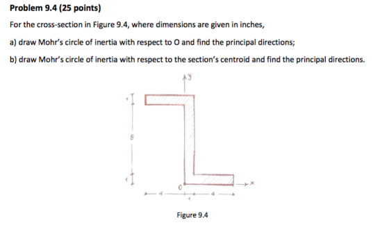
For the cross-section in figure 9.4, where dimensions are given in inches,
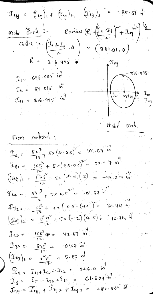
a) draw Mohr's circle of inertia with respect to O and find the principal directions;
b) draw Mohr's circle of inertia with respect to the section's centroid and find the principal directions.
Homework Answers


Add Answer to:
For the cross-section in figure 9.4, where dimensions are given
in inches,
a) draw Mohr's circle...
For the cross-section in figure 9.4, where dimensions are given in inches, a) draw Mohr's circle ...
 For the cross-section in figure 9.4, where dimensions are given
in inches,
a) draw Mohr's circle of inertia with respect to O and find the
principal directions;
b) draw Mohr's circle of inertia with respect to the section's
centroid and find the principal directions.
Problem 9.4 (25 points) For the cross-section in Figure 9.4, where dimensions are given in inches, a) draw Mohr's circle of inertia with respect to O and find the principal directions; b) draw Mohr's circle of...
For the cross-section in figure 9.4, where dimensions are given
in inches,
a) draw Mohr's circle of inertia with respect to O and find the
principal directions;
b) draw Mohr's circle of inertia with respect to the section's
centroid and find the principal directions.
Problem 9.4 (25 points) For the cross-section in Figure 9.4, where dimensions are given in inches, a) draw Mohr's circle of inertia with respect to O and find the principal directions; b) draw Mohr's circle of...
Please answer the following,and please note that 0.00130,0.00608,-0.000558 does not work. Mohr's circle is a graphical method used to determine an area's principal moments of inertia and to f...
 Please answer the following,and please note that
0.00130,0.00608,-0.000558 does not work.
Mohr's circle is a graphical method used to determine an area's principal moments of inertia and to find the orientation of the principal axes. Another advantage of using Mohr's circle is that it does not require that long equations be memorized. The method is as follows: 1. To construct Mohr's circle, begin by constructing a coordinate system with the moment of inertia, I, as the abscissa (x axis) and...
Please answer the following,and please note that
0.00130,0.00608,-0.000558 does not work.
Mohr's circle is a graphical method used to determine an area's principal moments of inertia and to find the orientation of the principal axes. Another advantage of using Mohr's circle is that it does not require that long equations be memorized. The method is as follows: 1. To construct Mohr's circle, begin by constructing a coordinate system with the moment of inertia, I, as the abscissa (x axis) and...
For the cross-section of the angle shown below, use Mohr's Circle to determine the orientation of...
 For the cross-section of the angle shown below, use Mohr's Circle to determine the orientation of the principal axes with origin O in degrees and the principal moments of inertia associated with these principal axes in in 4. (For e enter the value with the smallest magnitude.) 18.9 in 6.3 in >6.3 in 18.9 in- > Imax =
please make sure to also draw mohrs circle For the un-symmetric C-section shown below 1- Locate the centroid "C" 2- Detemine the principal axes and moments of inertia about the centroid....
 please make sure to also draw mohrs circle
For the un-symmetric C-section shown below 1- Locate the centroid "C" 2- Detemine the principal axes and moments of inertia about the centroid. 3- Detemine the moments and product of Inertia with respect to the u-v axes using Mohr's circle ye 0.5 in 6 in 4 in
For the un-symmetric C-section shown below 1- Locate the centroid "C" 2- Detemine the principal axes and moments of inertia about the centroid. 3- Detemine...
please make sure to also draw mohrs circle
For the un-symmetric C-section shown below 1- Locate the centroid "C" 2- Detemine the principal axes and moments of inertia about the centroid. 3- Detemine the moments and product of Inertia with respect to the u-v axes using Mohr's circle ye 0.5 in 6 in 4 in
For the un-symmetric C-section shown below 1- Locate the centroid "C" 2- Detemine the principal axes and moments of inertia about the centroid. 3- Detemine...
For the thick angle cross-section shown below, use Mohr's Circle to determine the orientation of ...
 For the thick angle cross-section shown below, use Mohr's Circle to determine the orientation of the principal centroidal axes in degrees and the principal moments of inertia associated with these principal axes in mm. (For,' enter the value with the smallest magnitude.) 143 mm 79 mm 143 mm 79 mm min max mm4 Transcript Request_Form From EPCC (1).pdf
For the thick angle cross-section shown below, use Mohr's Circle to determine the orientation of the principal centroidal axes in degrees and...
For the thick angle cross-section shown below, use Mohr's Circle to determine the orientation of the principal centroidal axes in degrees and the principal moments of inertia associated with these principal axes in mm. (For,' enter the value with the smallest magnitude.) 143 mm 79 mm 143 mm 79 mm min max mm4 Transcript Request_Form From EPCC (1).pdf
For the thick angle cross-section shown below, use Mohr's Circle to determine the orientation of the principal centroidal axes in degrees and...
Problem 1.8. Mohr's circle Draw Mohr's circle for the state of stress defined by 01 =...
 Problem 1.8. Mohr's circle Draw Mohr's circle for the state of stress defined by 01 = 80 MPa, 02 = -20 MPa and T12 = 40 MPa. Using this circle, (1) calculate the stress on axes rotated 60 degrees counterclock- wise from the reference axes, and (2) determine the principal stresses and the corresponding directions. Do these results agree with the results in section 1.3.3?
For the thick angle cross-section shown below, use Mohr's Circle to determine the orientation of the...
 For the thick angle cross-section shown below, use Mohr's Circle to determine the orientation of the principal centroidal axes in degrees and the principal moments of inertia associated with these principal axes in mm^4. (For theta_p, enter the value with the smallest magnitude.) theta_p = degree I_min = mm^4 I_max = mm^4
For the cross-section of the angle shown below, use Mohr's Circle to determine the orientation of...
 For the cross-section of the angle shown below, use Mohr's
Circle to determine the orientation of the centroidal principal
axes in degrees and the principal moments of inertia associated
with the centroidal principal axes in in4. (For
θp, enter the value with the smallest
magnitude.)
6.9 in
3.3 in
3.3 in
6.9 in
θp = °
Imin = in4
Imax = in4
3.3 in 6.9 in 3.3 in 6.9 in e34 min312.498 max827.428xin4 in
For the cross-section of the angle shown below, use Mohr's
Circle to determine the orientation of the centroidal principal
axes in degrees and the principal moments of inertia associated
with the centroidal principal axes in in4. (For
θp, enter the value with the smallest
magnitude.)
6.9 in
3.3 in
3.3 in
6.9 in
θp = °
Imin = in4
Imax = in4
3.3 in 6.9 in 3.3 in 6.9 in e34 min312.498 max827.428xin4 in
Class Activity Consider an unreinforced concrete beam cross section with the dimensions (in inches) shown in...
 Class Activity Consider an unreinforced concrete beam cross section with the dimensions (in inches) shown in the figure. The comcrete is sormal-weight with 6000 psi145Ib/f The section is subjected to a positive beading moment of 500 kip-ft about its horizontal axis causing compression and tension on the faces as shown. Assume the section remains elastic under this moment 15 Tension 20 Determine centroid of the section from the compression face. Answer: c-7.622 in (A) Determine moment of inertia of the...
PROBLEM 2: 40% A 6 kN force is exerted on the frame which has the T cross sectio analyze the states of stress at a section taken at 800 mm from the point of n shown below. It is required to 1. Fo...
 PROBLEM 2: 40% A 6 kN force is exerted on the frame which has the T cross sectio analyze the states of stress at a section taken at 800 mm from the point of n shown below. It is required to 1. For the given T cross section, find the centroid and the area moment of inertia I,. 2. Draw the free body diagram of the free end of the frame and determine the interna loadings at the centroid of...
 For the cross-section in figure 9.4, where dimensions are given
in inches,
a) draw Mohr's circle of inertia with respect to O and find the
principal directions;
b) draw Mohr's circle of inertia with respect to the section's
centroid and find the principal directions.
Problem 9.4 (25 points) For the cross-section in Figure 9.4, where dimensions are given in inches, a) draw Mohr's circle of inertia with respect to O and find the principal directions; b) draw Mohr's circle of...
For the cross-section in figure 9.4, where dimensions are given
in inches,
a) draw Mohr's circle of inertia with respect to O and find the
principal directions;
b) draw Mohr's circle of inertia with respect to the section's
centroid and find the principal directions.
Problem 9.4 (25 points) For the cross-section in Figure 9.4, where dimensions are given in inches, a) draw Mohr's circle of inertia with respect to O and find the principal directions; b) draw Mohr's circle of...
 Please answer the following,and please note that
0.00130,0.00608,-0.000558 does not work.
Mohr's circle is a graphical method used to determine an area's principal moments of inertia and to find the orientation of the principal axes. Another advantage of using Mohr's circle is that it does not require that long equations be memorized. The method is as follows: 1. To construct Mohr's circle, begin by constructing a coordinate system with the moment of inertia, I, as the abscissa (x axis) and...
Please answer the following,and please note that
0.00130,0.00608,-0.000558 does not work.
Mohr's circle is a graphical method used to determine an area's principal moments of inertia and to find the orientation of the principal axes. Another advantage of using Mohr's circle is that it does not require that long equations be memorized. The method is as follows: 1. To construct Mohr's circle, begin by constructing a coordinate system with the moment of inertia, I, as the abscissa (x axis) and...
 For the cross-section of the angle shown below, use Mohr's Circle to determine the orientation of the principal axes with origin O in degrees and the principal moments of inertia associated with these principal axes in in 4. (For e enter the value with the smallest magnitude.) 18.9 in 6.3 in >6.3 in 18.9 in- > Imax =
 please make sure to also draw mohrs circle
For the un-symmetric C-section shown below 1- Locate the centroid "C" 2- Detemine the principal axes and moments of inertia about the centroid. 3- Detemine the moments and product of Inertia with respect to the u-v axes using Mohr's circle ye 0.5 in 6 in 4 in
For the un-symmetric C-section shown below 1- Locate the centroid "C" 2- Detemine the principal axes and moments of inertia about the centroid. 3- Detemine...
please make sure to also draw mohrs circle
For the un-symmetric C-section shown below 1- Locate the centroid "C" 2- Detemine the principal axes and moments of inertia about the centroid. 3- Detemine the moments and product of Inertia with respect to the u-v axes using Mohr's circle ye 0.5 in 6 in 4 in
For the un-symmetric C-section shown below 1- Locate the centroid "C" 2- Detemine the principal axes and moments of inertia about the centroid. 3- Detemine...
 For the thick angle cross-section shown below, use Mohr's Circle to determine the orientation of the principal centroidal axes in degrees and the principal moments of inertia associated with these principal axes in mm. (For,' enter the value with the smallest magnitude.) 143 mm 79 mm 143 mm 79 mm min max mm4 Transcript Request_Form From EPCC (1).pdf
For the thick angle cross-section shown below, use Mohr's Circle to determine the orientation of the principal centroidal axes in degrees and...
For the thick angle cross-section shown below, use Mohr's Circle to determine the orientation of the principal centroidal axes in degrees and the principal moments of inertia associated with these principal axes in mm. (For,' enter the value with the smallest magnitude.) 143 mm 79 mm 143 mm 79 mm min max mm4 Transcript Request_Form From EPCC (1).pdf
For the thick angle cross-section shown below, use Mohr's Circle to determine the orientation of the principal centroidal axes in degrees and...
 Problem 1.8. Mohr's circle Draw Mohr's circle for the state of stress defined by 01 = 80 MPa, 02 = -20 MPa and T12 = 40 MPa. Using this circle, (1) calculate the stress on axes rotated 60 degrees counterclock- wise from the reference axes, and (2) determine the principal stresses and the corresponding directions. Do these results agree with the results in section 1.3.3?
 For the thick angle cross-section shown below, use Mohr's Circle to determine the orientation of the principal centroidal axes in degrees and the principal moments of inertia associated with these principal axes in mm^4. (For theta_p, enter the value with the smallest magnitude.) theta_p = degree I_min = mm^4 I_max = mm^4
 For the cross-section of the angle shown below, use Mohr's
Circle to determine the orientation of the centroidal principal
axes in degrees and the principal moments of inertia associated
with the centroidal principal axes in in4. (For
θp, enter the value with the smallest
magnitude.)
6.9 in
3.3 in
3.3 in
6.9 in
θp = °
Imin = in4
Imax = in4
3.3 in 6.9 in 3.3 in 6.9 in e34 min312.498 max827.428xin4 in
For the cross-section of the angle shown below, use Mohr's
Circle to determine the orientation of the centroidal principal
axes in degrees and the principal moments of inertia associated
with the centroidal principal axes in in4. (For
θp, enter the value with the smallest
magnitude.)
6.9 in
3.3 in
3.3 in
6.9 in
θp = °
Imin = in4
Imax = in4
3.3 in 6.9 in 3.3 in 6.9 in e34 min312.498 max827.428xin4 in
 Class Activity Consider an unreinforced concrete beam cross section with the dimensions (in inches) shown in the figure. The comcrete is sormal-weight with 6000 psi145Ib/f The section is subjected to a positive beading moment of 500 kip-ft about its horizontal axis causing compression and tension on the faces as shown. Assume the section remains elastic under this moment 15 Tension 20 Determine centroid of the section from the compression face. Answer: c-7.622 in (A) Determine moment of inertia of the...
 PROBLEM 2: 40% A 6 kN force is exerted on the frame which has the T cross sectio analyze the states of stress at a section taken at 800 mm from the point of n shown below. It is required to 1. For the given T cross section, find the centroid and the area moment of inertia I,. 2. Draw the free body diagram of the free end of the frame and determine the interna loadings at the centroid of...
Most questions answered within 3 hours.
-
A college student is employed as a door-to-door newspaper
salesman. Historical data suggests that the student...
asked 6 minutes ago -
Considering gravitational time dilation, calculate the time that
passes in Earth’s surface while 1 hour passes...
asked 30 minutes ago -
Minitab Problem: Take the Lake Hume June rainfall data and find
use the processes outlined in...
asked 1 hour ago -
X Company is trying to decide whether to continue using old
equipment to make Product A...
asked 1 hour ago -
IN PYTHON ONLY !! Program 2: Re-work
program #5 (WeeklyHours) from the previous assignment such that...
asked 2 hours ago -
The average length of time between arrivals at a turnpike
toll-booth is 26 seconds. What is...
asked 3 hours ago -
(a) A piston at 6.1 atm contains a gas that occupies a volume of
3.5 L....
asked 4 hours ago -
Please answer true or false. Words
cannot be changed or added in to make it true...
asked 4 hours ago -
An empty test tube weighs 15.923 grams. Then,
MgCl2•6H2O is added into the test tube. After...
asked 4 hours ago -
Assume memory access is 10 units of time and disk access is
10000 units of time....
asked 5 hours ago -
1. Are all good samples random?
2. Magazines often report surveys giving statistics such as “63%...
asked 5 hours ago -
Under all the various types of market structures, firms
must eventually earn some economic profits for...
asked 5 hours ago