
Homework Answers
Ans:(a)
(i)
Draw the circuit for t>0s
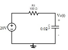
Apply nodal analysis at Vc(t)


Substitute:


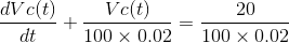


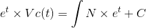
Solve the above differential equation:
This is a linear differential equation
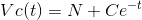
Integrating Factor 


Apply initial condtion , at t=0s Vc=0V


 ,
, 
(ii)

This is exponential graph:
(i) at t=0 ,


(ii)at t=2s


(iii) at 


(iii)
At steady state Vc=20V
Recall the formula of energy stored by a capacitor

Substitute


(iv)
Given: 


Therefore, Vc(t) will be 4V after 0.446s.
(b)
For t>Ts , circuit is at steady state.
Lets us shift our frame after t>Ts,
So, instant after t>Ts, will be considered t=0 in new frame
Redraw the circuit after t>Ts

Apply nodal analysis at Vc


Substitute:


Solve the above differential equation:
This is a linear differential equation
Integrating Factor 


Apply initial condtion , at t=0s Vc=20V


(ii)
This is exponentialy decaying curve
(i) at t=0s


(ii) at


Add Answer to:
Question B2 Figure 8 shows a DC electric circuit with a 2-way switch. The capacitor is...
R2 V. V. 2 R2 20 C1 3F Consider the circuit to be initially in steady state with switch S, connected to position a. Att Os, the switch transitions to position b. At t- 10s, the switch transitions bac...
 R2 V. V. 2 R2 20 C1 3F Consider the circuit to be initially in steady state with switch S, connected to position a. Att Os, the switch transitions to position b. At t- 10s, the switch transitions back to position a and stays there for the rest of time. Determine and roughly sketch Vc(t) for t > -2s
R2 V. V. 2 R2 20 C1 3F Consider the circuit to be initially in steady state with switch S, connected...
R2 V. V. 2 R2 20 C1 3F Consider the circuit to be initially in steady state with switch S, connected to position a. Att Os, the switch transitions to position b. At t- 10s, the switch transitions back to position a and stays there for the rest of time. Determine and roughly sketch Vc(t) for t > -2s
R2 V. V. 2 R2 20 C1 3F Consider the circuit to be initially in steady state with switch S, connected...
QUESTION Cyril the Circuit Analyst is examining the interaction of both AC and DC sources with a circuit. The circu...
 QUESTION Cyril the Circuit Analyst is examining the interaction of both AC and DC sources with a circuit. The circuit is drawn below. Pay careful attention to the arrows on the switches which show which are initially open, and which are initially closed. Assume that the capacitor is initially discharged at 0. All times are in seconds 10 mH 1-Os1-1s!=2s \ t = 5s 400 | 10cos(ox) 50 pF 10 mA At 0, the first switch closes connecting the current...
Question 4: RC Circuit: a) Charging capacitor: A simple RC circuit is given in Figure 4a....
 Question 4: RC Circuit: a) Charging capacitor: A simple RC circuit is given in Figure 4a. The capacitor is empty initially and switch was open for a long time. 4E, (V) EMF is used to charge the capacitor as switch is closed at t=0s. By using Kirchhoff's voltage law and Ohm's law that you learned so far, analyze this circuit and find the unknowns given below. 1)At t=0s. draw the equivalent circuit and find v. (Os), i. (Os), i (Os),...
In the circuit shown in Figure-2, the switch was in position-a for a long time. At...
 In the circuit shown in Figure-2, the switch was in position-a for a long time. At time t-0, the switch is moved to position-b. ) Att-0, calculate Vc(+). Q2: 151 1101 Solve Ve () at t20 Find Vc at t 2 sec. switch 25 Figure-2
Figure 1 shows a circuit after some switch-flipping and is now at time t = 0....
 Figure 1 shows a circuit after some switch-flipping and is now at time t = 0. It contains a capacitor that was charged to v.(0") = 75 V and an inductor that was charged to i (0°) = 3 A. 10) Is this circuit overdamped, underdamped, or critically damped [2 points A) Is this circuit displaying a natural or step response? (2 points) Solve for y(t) fort > 0 [8 points) +35w 13.230.išao Ous. "
Consider the circuit depicted in Fig. 2. The switch SW1 has been closed for a long time before it...
 Consider the circuit depicted in Fig. 2. The switch SW1 has been closed for a long time before it is opened at time t = 0. The switch SW2 has been open for a long time before it is closed att = 0.1 (sec). i) Find the initial current I(0) flowing in the inductor and the initial voltage V(0) across the capacitor. ii) Find the voltage V(t) across the capacitor and the current I(t) through the inductor for 0 ≤ t ≤...
(1) Consider the RC circuit shown in Figure 1. For t<0 the switch is open, and...
 (1) Consider the RC circuit shown in Figure 1. For t<0 the switch is open, and the charge stored on the capacitor is 0. At t-0 the switch is closed, and the voltage source begins charging the capacitor. Let R1-R2-220 Ω , C-0.47 μ F , Vs-5 V. (a) Write the differential equation as an expression for the capacitor voltage fort> 0 (i.e. write the differential equation) and calculate the time constant (b) Calculate the steady-state capacitor voltage R2 R1...
Consider the RC circuit in the figure. The switch has been open for a long time...
 Consider the RC circuit in the figure. The switch has been open for a long time and is closed at t=0s. The capacitor initially uncharged. (a) Immediately after the switch is closed, what is value of the current through each resistor? (b) After a long time has elapsed and the capacitor is fully charged, what is the value of the current through each resistor and the charge on the capacitor?
The switch in the circuit of Figure 1 has been in position A for a long...
 The switch in the circuit of Figure 1 has been in position A for a long time. At t-0, it is moved to position B The resulting step response of the series RLC circuit is described by the r differential equation (1). Figure 1 dt L dt LC LC The solution to equation (1) has two components the transient response vt(t) and the steady state response, Vss(t) v(t)v(t)+ Vss(t) The transient response v(t) is the same as that for the...
(3) The RL circuit shown in Figure 3 has a switch that is closed att 0....
 (3) The RL circuit shown in Figure 3 has a switch that is closed att 0. Assume that the circuit has reached steady state prior to the switch closing. You are given R1 1 kQ, R2-10 kQ, R3-R4-100 k2, L 10 mH, Vs-5 V. (a) [15 pts] Calculate the steady-state inductor current before the switch is closed (b) [16 pts] Give the differential equation as an expression of the inductor current fort>0 (i.e. write the differential equation) (c) 13 pts]...
 R2 V. V. 2 R2 20 C1 3F Consider the circuit to be initially in steady state with switch S, connected to position a. Att Os, the switch transitions to position b. At t- 10s, the switch transitions back to position a and stays there for the rest of time. Determine and roughly sketch Vc(t) for t > -2s
R2 V. V. 2 R2 20 C1 3F Consider the circuit to be initially in steady state with switch S, connected...
R2 V. V. 2 R2 20 C1 3F Consider the circuit to be initially in steady state with switch S, connected to position a. Att Os, the switch transitions to position b. At t- 10s, the switch transitions back to position a and stays there for the rest of time. Determine and roughly sketch Vc(t) for t > -2s
R2 V. V. 2 R2 20 C1 3F Consider the circuit to be initially in steady state with switch S, connected...
 QUESTION Cyril the Circuit Analyst is examining the interaction of both AC and DC sources with a circuit. The circuit is drawn below. Pay careful attention to the arrows on the switches which show which are initially open, and which are initially closed. Assume that the capacitor is initially discharged at 0. All times are in seconds 10 mH 1-Os1-1s!=2s \ t = 5s 400 | 10cos(ox) 50 pF 10 mA At 0, the first switch closes connecting the current...
 Question 4: RC Circuit: a) Charging capacitor: A simple RC circuit is given in Figure 4a. The capacitor is empty initially and switch was open for a long time. 4E, (V) EMF is used to charge the capacitor as switch is closed at t=0s. By using Kirchhoff's voltage law and Ohm's law that you learned so far, analyze this circuit and find the unknowns given below. 1)At t=0s. draw the equivalent circuit and find v. (Os), i. (Os), i (Os),...
 In the circuit shown in Figure-2, the switch was in position-a for a long time. At time t-0, the switch is moved to position-b. ) Att-0, calculate Vc(+). Q2: 151 1101 Solve Ve () at t20 Find Vc at t 2 sec. switch 25 Figure-2
 Figure 1 shows a circuit after some switch-flipping and is now at time t = 0. It contains a capacitor that was charged to v.(0") = 75 V and an inductor that was charged to i (0°) = 3 A. 10) Is this circuit overdamped, underdamped, or critically damped [2 points A) Is this circuit displaying a natural or step response? (2 points) Solve for y(t) fort > 0 [8 points) +35w 13.230.išao Ous. "
 (1) Consider the RC circuit shown in Figure 1. For t<0 the switch is open, and the charge stored on the capacitor is 0. At t-0 the switch is closed, and the voltage source begins charging the capacitor. Let R1-R2-220 Ω , C-0.47 μ F , Vs-5 V. (a) Write the differential equation as an expression for the capacitor voltage fort> 0 (i.e. write the differential equation) and calculate the time constant (b) Calculate the steady-state capacitor voltage R2 R1...
 Consider the RC circuit in the figure. The switch has been open for a long time and is closed at t=0s. The capacitor initially uncharged. (a) Immediately after the switch is closed, what is value of the current through each resistor? (b) After a long time has elapsed and the capacitor is fully charged, what is the value of the current through each resistor and the charge on the capacitor?
 The switch in the circuit of Figure 1 has been in position A for a long time. At t-0, it is moved to position B The resulting step response of the series RLC circuit is described by the r differential equation (1). Figure 1 dt L dt LC LC The solution to equation (1) has two components the transient response vt(t) and the steady state response, Vss(t) v(t)v(t)+ Vss(t) The transient response v(t) is the same as that for the...
 (3) The RL circuit shown in Figure 3 has a switch that is closed att 0. Assume that the circuit has reached steady state prior to the switch closing. You are given R1 1 kQ, R2-10 kQ, R3-R4-100 k2, L 10 mH, Vs-5 V. (a) [15 pts] Calculate the steady-state inductor current before the switch is closed (b) [16 pts] Give the differential equation as an expression of the inductor current fort>0 (i.e. write the differential equation) (c) 13 pts]...
Most questions answered within 3 hours.
-
. A 100.0 mL sample of 0.18 M HClO4 is titrated with 0.27 M
LiOH. Determine...
asked 7 minutes ago -
A regression equation that describes the relationship between
the amount of the bill ($) at a...
asked 1 hour ago -
exercise on VSEPR and molecular structrue.
octahedral
SeCl62-
TeCl62-
ClF62-
distorted
SeF62–
IF6–
asked 1 hour ago -
284 mL of a 0.52 M potassium hydroxide solution is added to 467
mL of a...
asked 1 hour ago -
Little’s Law: Val d’Costa is a world famous ski village in the
French Alps. Because of...
asked 2 hours ago -
Find the absolute error D for the calculation if A + B/C=D A=
9.4 +/- 0.4...
asked 2 hours ago -
New Air Heating and Cooling, manufactures furnaces and central
air units. The company pride itself on...
asked 2 hours ago -
A coach uses a new technique to train gymnasts. Seven
gymnasts were randomly selected and their...
asked 4 hours ago -
While rotating the tires on your car you notice a rock [mass =
0.1 Kg] stuck...
asked 6 hours ago -
Using MARS simulator, write MIPS programs according to
the following scenarios: Receive a positive integer number...
asked 8 hours ago -
An object in front of a concave mirror has a real image that is
11.5 cm...
asked 8 hours ago -
Consider the reaction, C3 H8 + O2 --> CO2 + H2O. How many
moles of O2...
asked 10 hours ago