
Homework Answers
![moment about E. (Ro*1) - (1X0.288*1) - (2x2).(x los 45°) =0 R - 6,268 -4 - 070% so Road.97N JC Right ward] Rear 4.268w C Loft](http://img.homeworklib.com/questions/b81f16e0-4d5f-11eb-a059-1179da61949d.png?x-oss-process=image/resize,w_560)
Add Answer to:
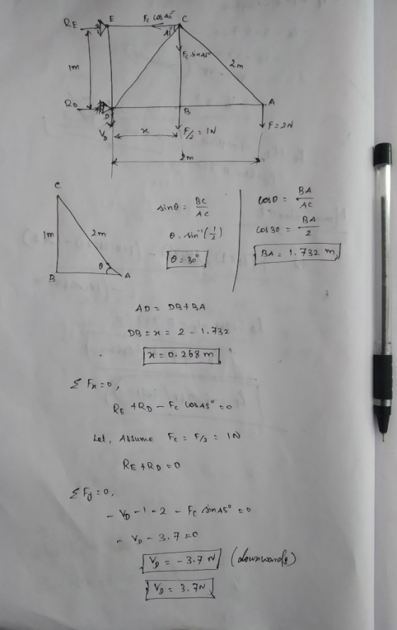
Consider the structure in Figure 3. We will study the forces in the bars of this...
Write the MATLAB code and use the function linsolve() to solve the system of linear equations. Thank you! l Truss A truss is a structure that typically consists of 1. All straight members 2. connected...
 Write the MATLAB code and use the function linsolve() to solve
the system of linear equations.
Thank you!
l Truss A truss is a structure that typically consists of 1. All straight members 2. connected together with pin joints 3. connected only at the ends of the members 4. and all external forces (loads&reactions) must be applied only at the joints. The weights of the members may be neglected. The basic building block of a truss is a triangle. Large...
Write the MATLAB code and use the function linsolve() to solve
the system of linear equations.
Thank you!
l Truss A truss is a structure that typically consists of 1. All straight members 2. connected together with pin joints 3. connected only at the ends of the members 4. and all external forces (loads&reactions) must be applied only at the joints. The weights of the members may be neglected. The basic building block of a truss is a triangle. Large...
Learning Goal: To solve for forces in statically indeterminate bars with axial loads. Consider a new...
 Learning Goal: To solve for forces in statically indeterminate bars with axial loads. Consider a new structure, where the thickness of the bar is reduced to 32.5 mm from C to B (it is still square) (Figure 2) and <= 3.75 m. If the applied load is F - 370 kN , then what is the reaction at ? Let a positive reaction act to the right. The total length is still 6 m Express your answer with appropriate units...
Problem 1 The truss (all joints are pinned) structure in figure 1 is made of members with cross s...
 We were unable to transcribe this imageProblem 1 The truss (all joints are pinned) structure in figure 1 is made of members with cross sectional area A = 1 in, with a linear elastic, homogeneous, isotropic material with an elastic modulus. E-10E6 psi and a coefficient of thermal expansion, α-6E-6 °F-ι. The structure starts out at a uniform temperature of 65°F and is raised to a final temperature of 120°F while being subjected to a concentrated load Po- 5,000 lbs...
Question 3 The structure shown in Figure Q(3) is a two-bar truss with spring support. Both bars have modulus of elasticity and cross-sectional area of E- 210 GPa and A -5.0 x10 m. Bar one has...
 Question 3 The structure shown in Figure Q(3) is a two-bar truss with spring support. Both bars have modulus of elasticity and cross-sectional area of E- 210 GPa and A -5.0 x10 m. Bar one has a length of 5 m and bar two a length of 10 m. The spring stiffness is k -2000 kN/m. CVE 4303(F) Page 2 of 4 Determine (a) the stiffness matrix for each of the three elements (15 marks) (b) the normal stresses in...
The structure below is supported by a pin at A and a roller at E Determine the force in each memb...
 The structure below is supported by a pin at A and a roller at E Determine the force in each member of the truss using the Method of Joints H meters 2 FE m AH m GF m HG m Joint Loadings, kN ent length, m Height, m HG GF FE 1.5 2 Draw FBD of truss system to determine reaction forces Assume all forces in members are tensile. If answer is negative, force is compressive. s in x direction...
Using the stiffness method, determine the axial forces within members and the displacements of jo...
 Using the stiffness method, determine the axial forces within
members and the displacements of joints of the truss shown in the
Figure 1. The truss was built using 50 mm x 50 mm x 3 mm SHS with
E= 200 GPa (approx). (Cross members BD and CE are not connected at
the middle)
(a) Show local stiffness matrices for each member and the
assembled global stiffness matrix. Show your step by step solution.
(30 Marks)
(b) Use an appropriate method...
Using the stiffness method, determine the axial forces within
members and the displacements of joints of the truss shown in the
Figure 1. The truss was built using 50 mm x 50 mm x 3 mm SHS with
E= 200 GPa (approx). (Cross members BD and CE are not connected at
the middle)
(a) Show local stiffness matrices for each member and the
assembled global stiffness matrix. Show your step by step solution.
(30 Marks)
(b) Use an appropriate method...
Grid 4 Grid 3 Po 15 in Grid 1 Grid 2 10 in Figure 1: Problem...
 Grid 4 Grid 3 Po 15 in Grid 1 Grid 2 10 in Figure 1: Problem 1 Schematic Problem 1 The truss (all joints are pinned) structure in figure 1 is made of members with cross sectional area A- 1 in2, with a linear elastic, homogeneous, isotropic material with an elastic modulus, E, 10E6 psi and a coefficient of thermal expansion. α-6E-6 op-1. The structure starts out at a uniform temperature of 65°F and is raised to a final temperature...
To solve for forces in statically indeterminate bars with axial loads.
 To solve for forces in statically indeterminate bars with axial loads.When the number of reaction forces is greater than the number of equilibrium equations, the system is statically indeterminate. Solving for the reactions requires some additional equations. These additional equations come from considering compatibility relationships (i.e.) continuity of displacements and relationships between displacements and loads).For an axially loaded member, the compatibility relationship for the deflections can be written by setting the total relative axial displacement between the ends of the...
Class Rosder Number Print Last Name (only) 3. In the figure below, you have a pin...
 Class Rosder Number Print Last Name (only) 3. In the figure below, you have a pin support at 4 and a roller support at &. Use the method of joints to determine the axial forces in each member of the truss. State whether the member is acting in tension or compression. (Measure Outcomes "a and e) (25-points) 3 ft 3 ft 2 kip
 Write the MATLAB code and use the function linsolve() to solve
the system of linear equations.
Thank you!
l Truss A truss is a structure that typically consists of 1. All straight members 2. connected together with pin joints 3. connected only at the ends of the members 4. and all external forces (loads&reactions) must be applied only at the joints. The weights of the members may be neglected. The basic building block of a truss is a triangle. Large...
Write the MATLAB code and use the function linsolve() to solve
the system of linear equations.
Thank you!
l Truss A truss is a structure that typically consists of 1. All straight members 2. connected together with pin joints 3. connected only at the ends of the members 4. and all external forces (loads&reactions) must be applied only at the joints. The weights of the members may be neglected. The basic building block of a truss is a triangle. Large...
 Learning Goal: To solve for forces in statically indeterminate bars with axial loads. Consider a new structure, where the thickness of the bar is reduced to 32.5 mm from C to B (it is still square) (Figure 2) and <= 3.75 m. If the applied load is F - 370 kN , then what is the reaction at ? Let a positive reaction act to the right. The total length is still 6 m Express your answer with appropriate units...
 We were unable to transcribe this imageProblem 1 The truss (all joints are pinned) structure in figure 1 is made of members with cross sectional area A = 1 in, with a linear elastic, homogeneous, isotropic material with an elastic modulus. E-10E6 psi and a coefficient of thermal expansion, α-6E-6 °F-ι. The structure starts out at a uniform temperature of 65°F and is raised to a final temperature of 120°F while being subjected to a concentrated load Po- 5,000 lbs...
 Question 3 The structure shown in Figure Q(3) is a two-bar truss with spring support. Both bars have modulus of elasticity and cross-sectional area of E- 210 GPa and A -5.0 x10 m. Bar one has a length of 5 m and bar two a length of 10 m. The spring stiffness is k -2000 kN/m. CVE 4303(F) Page 2 of 4 Determine (a) the stiffness matrix for each of the three elements (15 marks) (b) the normal stresses in...
 The structure below is supported by a pin at A and a roller at E Determine the force in each member of the truss using the Method of Joints H meters 2 FE m AH m GF m HG m Joint Loadings, kN ent length, m Height, m HG GF FE 1.5 2 Draw FBD of truss system to determine reaction forces Assume all forces in members are tensile. If answer is negative, force is compressive. s in x direction...
 Using the stiffness method, determine the axial forces within
members and the displacements of joints of the truss shown in the
Figure 1. The truss was built using 50 mm x 50 mm x 3 mm SHS with
E= 200 GPa (approx). (Cross members BD and CE are not connected at
the middle)
(a) Show local stiffness matrices for each member and the
assembled global stiffness matrix. Show your step by step solution.
(30 Marks)
(b) Use an appropriate method...
Using the stiffness method, determine the axial forces within
members and the displacements of joints of the truss shown in the
Figure 1. The truss was built using 50 mm x 50 mm x 3 mm SHS with
E= 200 GPa (approx). (Cross members BD and CE are not connected at
the middle)
(a) Show local stiffness matrices for each member and the
assembled global stiffness matrix. Show your step by step solution.
(30 Marks)
(b) Use an appropriate method...
 Grid 4 Grid 3 Po 15 in Grid 1 Grid 2 10 in Figure 1: Problem 1 Schematic Problem 1 The truss (all joints are pinned) structure in figure 1 is made of members with cross sectional area A- 1 in2, with a linear elastic, homogeneous, isotropic material with an elastic modulus, E, 10E6 psi and a coefficient of thermal expansion. α-6E-6 op-1. The structure starts out at a uniform temperature of 65°F and is raised to a final temperature...
 Class Rosder Number Print Last Name (only) 3. In the figure below, you have a pin support at 4 and a roller support at &. Use the method of joints to determine the axial forces in each member of the truss. State whether the member is acting in tension or compression. (Measure Outcomes "a and e) (25-points) 3 ft 3 ft 2 kip
Most questions answered within 3 hours.
-
You are attempting to calculate a firm’s free cash flow to
equity. You know the following...
asked 44 minutes ago -
the following reaction occurs in a balloon containing
N2O2 gas
N2O4(g)=2NO2(g)
will the volume of the...
asked 1 hour ago -
answer the questions throughout this program
public class Day implements Comparable {
Private Boolean atWork;...
asked 1 hour ago -
This is C++ code for parking fee management program
#include <iostream>
#include <iomanip>
using namespace std;...
asked 1 hour ago -
The free energy change for the following reaction at 25 °C, when
[Sn2+] = 1.17 M...
asked 3 hours ago -
An MNE is this kind of industry when competition in one country
is essentially independent of...
asked 4 hours ago -
. For this set of questions, determine what
proportion of a normal distribution is located betweeneach...
asked 5 hours ago -
A college student is employed as a door-to-door newspaper
salesman. Historical data suggests that the student...
asked 6 hours ago -
MATLAB HW 11 problem using Switch Case and Input commands
Write a script file that calculates...
asked 6 hours ago -
Considering gravitational time dilation, calculate the time that
passes in Earth’s surface while 1 hour passes...
asked 6 hours ago -
Minitab Problem: Take the Lake Hume June rainfall data and find
use the processes outlined in...
asked 7 hours ago -
X Company is trying to decide whether to continue using old
equipment to make Product A...
asked 7 hours ago