

Homework Answers

 PLEASE TAKE CARE ABOUT THE
SIGNS.BECUASE IF YOU TAKE WRONG SIGN THEN ENTIRE PROBLEM WILL
WRONG
PLEASE TAKE CARE ABOUT THE
SIGNS.BECUASE IF YOU TAKE WRONG SIGN THEN ENTIRE PROBLEM WILL
WRONG
THANK YOU HAVE A NICE DAY
Add Answer to:
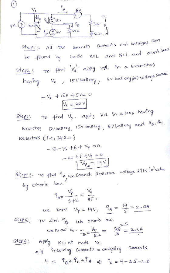
2. Consider the resistive circuit below. 6V 133 + 15V R3 lc R1 80 V 4A...
In the circuit below, find the currents and their directions. R1 R5 80 12 BAT1 6V...
 In the circuit below, find the currents and their directions. R1 R5 80 12 BAT1 6V R2 2012 BAT2 3 V R4 62 R3 922 BAT3 8V
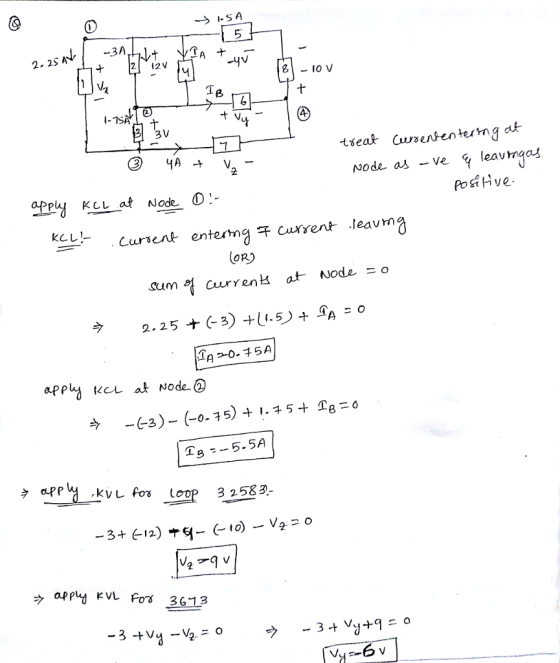
Problemuǐ(30 points) Consider the circuit in Figure 1 1Ω 4A Figure I. DC resistive circuit Submit...
 Problemuǐ(30 points) Consider the circuit in Figure 1 1Ω 4A Figure I. DC resistive circuit Submit these Numerical Values in the Answer Sheet 5 points:IA 5 points: IA 5 points:VV 5 points: V.V 5 points : Power of the 2 Ω resistor Li 5 points: Power of the current source [W 1.a : Use KCL, KVL, and Ohm's Law to calculate 1 [AJ. I2 IA]. V1 IV] and V2 [V] 工 20-120 A 112 2. L.b: Verify your results by...
R1 R2 V S R3 R4 For the circuit above, Vs 100 V, R1 220 2,...
 R1 R2 V S R3 R4 For the circuit above, Vs 100 V, R1 220 2, R2- 330 2, R3 470 2 and R4 560 Q. Use any circuit reduction and calculation techniques learned so far to find the power absorbed by R2 PR2 1.80 W PR2 5.09 W O PR2-3.39 w PR2 2.14 W
1) In the circuit below the currents are named A, and lc The current direction is determined by the source (out of positive terminal) in the middle and right branches and is clockwise in the left bra...
 1) In the circuit below the currents are named A, and lc The current direction is determined by the source (out of positive terminal) in the middle and right branches and is clockwise in the left branch · IA flows through R2 and R1 Is flows through R4 and Vb cflows through R3, Vc AB R2 R3 R4 R1 Vb a) Draw the circuit and show the 3 currents described above, including arrows showing the current direction. Show the voltage...
Problem 4a (15 points) For the transistor circuit shown in the figure, calculate the value of...
 Problem 4a (15 points) For the transistor circuit shown in the figure, calculate the value of the output voltage given β 49 and VBE-0.7V. Problem 4b (10 points) The charge entering an electric element (part) is shown in the figure. Find the current at t- 1.5 sec, t-2.5 sec and t 10 sec 30 0 246810 12 Problem 3 (25 points) For the circuit shown in the Figure, use the Mesh Analysis method, to find the value of the branch...
Name: ID: 2. For the circuit shown below R1=40, R2=40, and R3=40 circuit shown below in...
 Name: ID: 2. For the circuit shown below R1=40, R2=40, and R3=40 circuit shown below in Figure 2. perform Thevenin Equivalent circuit analysis. Vs= 10V, a. Find the Thevenin Resistance b. Find the Thevenin Voltage C. Show the Equivalent Circuit d. Find the maximum power transfer to the load ingina Figure 2
explain clearly and step by step using to study for final exam. will rate tthanks Problem 1: Consider the electrical circuit below and assume R1 = 12Ω, 10Ω, R3-9 Ω, R4-8 Ω, i,-3A, and v.-2 V. Using,...
 explain clearly and step by step using to study for final exam.
will rate tthanks
Problem 1: Consider the electrical circuit below and assume R1 = 12Ω, 10Ω, R3-9 Ω, R4-8 Ω, i,-3A, and v.-2 V. Using, Node-Voltage method, please, find the voltages vi, U2, v3 and the current i depicted in the figure. R1 Vs 1V2 VI RA releience Node .
Problem 1: Consider the electrical circuit below and assume R1 = 12Ω, 10Ω, R3-9 Ω, R4-8 Ω, i,-3A,...
explain clearly and step by step using to study for final exam.
will rate tthanks
Problem 1: Consider the electrical circuit below and assume R1 = 12Ω, 10Ω, R3-9 Ω, R4-8 Ω, i,-3A, and v.-2 V. Using, Node-Voltage method, please, find the voltages vi, U2, v3 and the current i depicted in the figure. R1 Vs 1V2 VI RA releience Node .
Problem 1: Consider the electrical circuit below and assume R1 = 12Ω, 10Ω, R3-9 Ω, R4-8 Ω, i,-3A,...
2- Set the two independent power sources to Vsi 6V and Veo" 10 V and measure...
 2- Set the two independent power sources to Vsi 6V and Veo" 10 V and measure their actual values using the DMM. Actual Values of power sources: 4.47 VS15.99 Vs- 3- Using the breadboard construct the circuit shown in Figure 4,1 (repeated below for convenience). Use the resistors measured in Step 1 (above) and the power sources Vsi- 6 V, and Vs2 -10 V. IR3 IRI RS. R5 R1 R3 Va V4 V2 V1 ww ww It 12 R4 R23...
Question I : Consider the amplifier circuit shown below (p-150 for both transistors) (18 marks) +12V R4 1k8 R1 15k Q1 2N3904 C2+ 10μ R2 6V 4k7 2mA Out Q2 2N3904 C1 R3 10k R5 1k8 In 10H (i) Perform...
 Question I : Consider the amplifier circuit shown below (p-150 for both transistors) (18 marks) +12V R4 1k8 R1 15k Q1 2N3904 C2+ 10μ R2 6V 4k7 2mA Out Q2 2N3904 C1 R3 10k R5 1k8 In 10H (i) Perform DC analysis and prove that the indicated voltages and currents in the figure are correctly calculated. Find the operating point of Q1 and Q2 (5 marks) (ii) Calculate the gain of this amplifier (5 marks) (iii) In the lab, only...
 In the circuit below, find the currents and their directions. R1 R5 80 12 BAT1 6V R2 2012 BAT2 3 V R4 62 R3 922 BAT3 8V
 Problemuǐ(30 points) Consider the circuit in Figure 1 1Ω 4A Figure I. DC resistive circuit Submit these Numerical Values in the Answer Sheet 5 points:IA 5 points: IA 5 points:VV 5 points: V.V 5 points : Power of the 2 Ω resistor Li 5 points: Power of the current source [W 1.a : Use KCL, KVL, and Ohm's Law to calculate 1 [AJ. I2 IA]. V1 IV] and V2 [V] 工 20-120 A 112 2. L.b: Verify your results by...
 R1 R2 V S R3 R4 For the circuit above, Vs 100 V, R1 220 2, R2- 330 2, R3 470 2 and R4 560 Q. Use any circuit reduction and calculation techniques learned so far to find the power absorbed by R2 PR2 1.80 W PR2 5.09 W O PR2-3.39 w PR2 2.14 W
 1) In the circuit below the currents are named A, and lc The current direction is determined by the source (out of positive terminal) in the middle and right branches and is clockwise in the left branch · IA flows through R2 and R1 Is flows through R4 and Vb cflows through R3, Vc AB R2 R3 R4 R1 Vb a) Draw the circuit and show the 3 currents described above, including arrows showing the current direction. Show the voltage...
 Problem 4a (15 points) For the transistor circuit shown in the figure, calculate the value of the output voltage given β 49 and VBE-0.7V. Problem 4b (10 points) The charge entering an electric element (part) is shown in the figure. Find the current at t- 1.5 sec, t-2.5 sec and t 10 sec 30 0 246810 12 Problem 3 (25 points) For the circuit shown in the Figure, use the Mesh Analysis method, to find the value of the branch...
 Name: ID: 2. For the circuit shown below R1=40, R2=40, and R3=40 circuit shown below in Figure 2. perform Thevenin Equivalent circuit analysis. Vs= 10V, a. Find the Thevenin Resistance b. Find the Thevenin Voltage C. Show the Equivalent Circuit d. Find the maximum power transfer to the load ingina Figure 2
 explain clearly and step by step using to study for final exam.
will rate tthanks
Problem 1: Consider the electrical circuit below and assume R1 = 12Ω, 10Ω, R3-9 Ω, R4-8 Ω, i,-3A, and v.-2 V. Using, Node-Voltage method, please, find the voltages vi, U2, v3 and the current i depicted in the figure. R1 Vs 1V2 VI RA releience Node .
Problem 1: Consider the electrical circuit below and assume R1 = 12Ω, 10Ω, R3-9 Ω, R4-8 Ω, i,-3A,...
explain clearly and step by step using to study for final exam.
will rate tthanks
Problem 1: Consider the electrical circuit below and assume R1 = 12Ω, 10Ω, R3-9 Ω, R4-8 Ω, i,-3A, and v.-2 V. Using, Node-Voltage method, please, find the voltages vi, U2, v3 and the current i depicted in the figure. R1 Vs 1V2 VI RA releience Node .
Problem 1: Consider the electrical circuit below and assume R1 = 12Ω, 10Ω, R3-9 Ω, R4-8 Ω, i,-3A,...
 2- Set the two independent power sources to Vsi 6V and Veo" 10 V and measure their actual values using the DMM. Actual Values of power sources: 4.47 VS15.99 Vs- 3- Using the breadboard construct the circuit shown in Figure 4,1 (repeated below for convenience). Use the resistors measured in Step 1 (above) and the power sources Vsi- 6 V, and Vs2 -10 V. IR3 IRI RS. R5 R1 R3 Va V4 V2 V1 ww ww It 12 R4 R23...
 Question I : Consider the amplifier circuit shown below (p-150 for both transistors) (18 marks) +12V R4 1k8 R1 15k Q1 2N3904 C2+ 10μ R2 6V 4k7 2mA Out Q2 2N3904 C1 R3 10k R5 1k8 In 10H (i) Perform DC analysis and prove that the indicated voltages and currents in the figure are correctly calculated. Find the operating point of Q1 and Q2 (5 marks) (ii) Calculate the gain of this amplifier (5 marks) (iii) In the lab, only...
Most questions answered within 3 hours.
-
In Drosophila, the transition from the syncytial blastoderm
stage to the cellular blastoderm stage is a...
asked 7 minutes ago -
Project management question:
Name 3 different types of resources (hint: humans are one
type)
asked 20 minutes ago -
Consider the following reaction: C 2H 2( g) + 2H 2( g) C 2H 6(
g)...
asked 27 minutes ago -
Consider a 1.0 L buffer containing 0.092 mol L-1 HCOOH and 0.100
mol L-1 HCOO-. What...
asked 36 minutes ago -
Koch Realty has owned a vacant land with a FMV of
$775,000 and an adjusted basis...
asked 42 minutes ago -
It is estimated 29% of all adults in United States invest in
stocks and that 85%...
asked 42 minutes ago -
What does a 2-sided p value of 0.04 mean? (I am not asking if it
is...
asked 56 minutes ago -
A parallel-plate capacitor is made from two aluminum-foil
sheets, each 7.8 cmcm wide and 5.1 mmlong....
asked 57 minutes ago -
1. why is toluene a stronger nucleophile than benzene?
2.why is phenol a stronger nucleophile than...
asked 1 hour ago -
4. How can you solve for the density of the liquid from the
slope? Please show...
asked 1 hour ago -
when 2053 j of heat is added to 46.3 g of hexane C6H14 the
temperature increases...
asked 1 hour ago -
I need new and unique answers, please. (Use your own words,
don't copy and paste), Please...
asked 1 hour ago