
Homework Answers

Matlab code:

Add Answer to:
solve using matlab
For the circuit below, to what value should the load impedance ZLD be...
Problem 1. Perform the following for the circuit below using the node voltage method: 10Ω 10Ω...
 Problem 1. Perform the following for the circuit below using the node voltage method: 10Ω 10Ω 5i a) Calculate ia b) Calculate v c) Calculate Psource,5ia Problem 2. Perform the following for the circuit below using the node voltage method: 10Ω 1 4Ω 2 60V+ 30A V. 3 2Ω 5Ω 3 a) Calculate vi, v2 and vs b) Calculate Psource 30A c) Calculate Psource,Gov node voltage method Problem 3. Perform the following for the circuit below using the 10V 4Ω...
ame Su chool Number 4: : The source voltage of the circuit below is V()-140cos(30). The component values are RI-20, XL-30. Xc-20 a) Determine the load impedance Zab that will absorb maximum power if...
 ame Su chool Number 4: : The source voltage of the circuit below is V()-140cos(30). The component values are RI-20, XL-30. Xc-20 a) Determine the load impedance Zab that will absorb maximum power if it is connected to terminals a-b of the circuit below. b) Determine the maximum power absorbed by this load. Xc XL. M-0.8H R1 2-2 0.4H Vit)
ame Su chool Number 4: : The source voltage of the circuit below is V()-140cos(30). The component values are RI-20,...
ame Su chool Number 4: : The source voltage of the circuit below is V()-140cos(30). The component values are RI-20, XL-30. Xc-20 a) Determine the load impedance Zab that will absorb maximum power if it is connected to terminals a-b of the circuit below. b) Determine the maximum power absorbed by this load. Xc XL. M-0.8H R1 2-2 0.4H Vit)
ame Su chool Number 4: : The source voltage of the circuit below is V()-140cos(30). The component values are RI-20,...
Assuming that the load impedance is to be purely resistive, what load should be connected to...
 Assuming that the load impedance is to be purely resistive, what load should be connected to terminals a-b of the circuits in the given figure so that the maximum power is transferred to the load? Assume R 52 Ω. 100 Ω -j10Ω 40Ω 120/60° v (+ 2/90 A j30 Ω o b The value of R is Ω.
Q4: For the circuit shown in figure below, find the value of impedance Z that will...
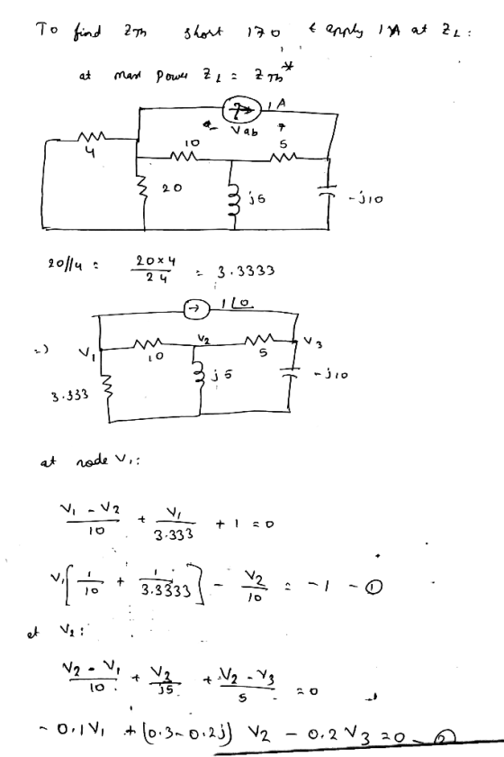
 Q4: For the circuit shown in figure below, find the value of impedance Z that will receive maximum power, and determine this power. (15Marks) 85 22 -j10022 170 20° V 200000 j2002 50 22
Questions: For circuit A5-1 below, solve for the total internal impedance (resistance and reactance) of each...
 Questions: For circuit A5-1 below, solve for the total internal impedance (resistance and reactance) of each transformer 1) referred to its primary side (ZAB, Zec) Write answer in phasor form. (4 marks) For circuit A5-1 below, given that the input voltage to transformer BC is 225 KVZ0°, and Z is 300Z15°, solve for %VR = 2NL-V2FL x 100% V2FL (3 marks) the voltage regulation of transformer BC for the connected load. For circuit A5-1 below, given that the input voltage...
5. In the circuit below the power source with the source impedance of Z, "wakes up"...
 5. In the circuit below the power source with the source impedance of Z, "wakes up" at t=0 and goes from O V to 3 V-that voltage is routed to the interface via a motherboard trace with characteristic impedance Z, and total signal propagation time through it of 10 ns; the interface is approximated with a load impedance Z (see schematics below). The Load is intended for the value of stead-state voltage from this source, but can tolerate voltage surges...
(9) Determine the amount of power the 4 A current source delivers to the circuit below....
 (9) Determine the amount of power the 4 A current source delivers to the circuit below. (Solve using the mesh-current method only, but reflect on the complexity of using node-voltage (Source: Nilsson and Reidel, 9th edition.) 4Ω 120 V 20 Ω 80 V 702 1Ω 4 A
In the circuit shown below, Vs 20cos (377t). Determine the impedance value Zi that would result...
 In the circuit shown below, Vs 20cos (377t). Determine the impedance value Zi that would result in maximum real power transfer to the load. Also, determine the value of Pmax. Hint: maximum power transfer occurs when Z Zth* 3. 5 3. Determine (by inspection) the bus admittance matrix (Ybus) for the circuit shown below. -j0.50 jo.4Ω j0.20 1.02 0.8Ω . 12 0.2Ω 5.00 210 1.0Ω jo.25Ω -j0.1Ω 4/30 A
Solve by hand and simulate in any electrical circuit simulator preferrably LTSpice Solve by hand only. Problem #4: Consider the circuit shown below. 6Ω /8 Ω 302 2700 V (rms) 40 2 Source-Line Load...
 Solve by hand and simulate in any electrical circuit
simulator preferrably LTSpice
Solve by hand only.
Problem #4: Consider the circuit shown below. 6Ω /8 Ω 302 2700 V (rms) 40 2 Source-Line Load (a) Find the real power dissipated in the line. (b) Find the capacitive reactance that when connected in parallel with the load will pl make the load look purely resistive. (c) What is the equivalent impedance of the load in (b)? (d) Find the real power...
Solve by hand and simulate in any electrical circuit
simulator preferrably LTSpice
Solve by hand only.
Problem #4: Consider the circuit shown below. 6Ω /8 Ω 302 2700 V (rms) 40 2 Source-Line Load (a) Find the real power dissipated in the line. (b) Find the capacitive reactance that when connected in parallel with the load will pl make the load look purely resistive. (c) What is the equivalent impedance of the load in (b)? (d) Find the real power...
a. The value of the voltage source and all the load impedances of AC circuit in...
 a. The value of the voltage source and all the load impedances of AC circuit in Figure Q2(a) are given as list below; 21 Z3 V. Z2 ZA Figure Q2(a) Calculate the real and reactive power absorbed by load impedances and (C01: P01 - 8 marks) ii. Determine the power factor at the load impedance, (C01: P01 - 2 marks) a. The value of the voltage source and all the load impedances of AC circuit in Figure Q2(a) are given...
 Problem 1. Perform the following for the circuit below using the node voltage method: 10Ω 10Ω 5i a) Calculate ia b) Calculate v c) Calculate Psource,5ia Problem 2. Perform the following for the circuit below using the node voltage method: 10Ω 1 4Ω 2 60V+ 30A V. 3 2Ω 5Ω 3 a) Calculate vi, v2 and vs b) Calculate Psource 30A c) Calculate Psource,Gov node voltage method Problem 3. Perform the following for the circuit below using the 10V 4Ω...
 ame Su chool Number 4: : The source voltage of the circuit below is V()-140cos(30). The component values are RI-20, XL-30. Xc-20 a) Determine the load impedance Zab that will absorb maximum power if it is connected to terminals a-b of the circuit below. b) Determine the maximum power absorbed by this load. Xc XL. M-0.8H R1 2-2 0.4H Vit)
ame Su chool Number 4: : The source voltage of the circuit below is V()-140cos(30). The component values are RI-20,...
ame Su chool Number 4: : The source voltage of the circuit below is V()-140cos(30). The component values are RI-20, XL-30. Xc-20 a) Determine the load impedance Zab that will absorb maximum power if it is connected to terminals a-b of the circuit below. b) Determine the maximum power absorbed by this load. Xc XL. M-0.8H R1 2-2 0.4H Vit)
ame Su chool Number 4: : The source voltage of the circuit below is V()-140cos(30). The component values are RI-20,...
 Assuming that the load impedance is to be purely resistive, what load should be connected to terminals a-b of the circuits in the given figure so that the maximum power is transferred to the load? Assume R 52 Ω. 100 Ω -j10Ω 40Ω 120/60° v (+ 2/90 A j30 Ω o b The value of R is Ω.
 Q4: For the circuit shown in figure below, find the value of impedance Z that will receive maximum power, and determine this power. (15Marks) 85 22 -j10022 170 20° V 200000 j2002 50 22
 Questions: For circuit A5-1 below, solve for the total internal impedance (resistance and reactance) of each transformer 1) referred to its primary side (ZAB, Zec) Write answer in phasor form. (4 marks) For circuit A5-1 below, given that the input voltage to transformer BC is 225 KVZ0°, and Z is 300Z15°, solve for %VR = 2NL-V2FL x 100% V2FL (3 marks) the voltage regulation of transformer BC for the connected load. For circuit A5-1 below, given that the input voltage...
 5. In the circuit below the power source with the source impedance of Z, "wakes up" at t=0 and goes from O V to 3 V-that voltage is routed to the interface via a motherboard trace with characteristic impedance Z, and total signal propagation time through it of 10 ns; the interface is approximated with a load impedance Z (see schematics below). The Load is intended for the value of stead-state voltage from this source, but can tolerate voltage surges...
 (9) Determine the amount of power the 4 A current source delivers to the circuit below. (Solve using the mesh-current method only, but reflect on the complexity of using node-voltage (Source: Nilsson and Reidel, 9th edition.) 4Ω 120 V 20 Ω 80 V 702 1Ω 4 A
 In the circuit shown below, Vs 20cos (377t). Determine the impedance value Zi that would result in maximum real power transfer to the load. Also, determine the value of Pmax. Hint: maximum power transfer occurs when Z Zth* 3. 5 3. Determine (by inspection) the bus admittance matrix (Ybus) for the circuit shown below. -j0.50 jo.4Ω j0.20 1.02 0.8Ω . 12 0.2Ω 5.00 210 1.0Ω jo.25Ω -j0.1Ω 4/30 A
 Solve by hand and simulate in any electrical circuit
simulator preferrably LTSpice
Solve by hand only.
Problem #4: Consider the circuit shown below. 6Ω /8 Ω 302 2700 V (rms) 40 2 Source-Line Load (a) Find the real power dissipated in the line. (b) Find the capacitive reactance that when connected in parallel with the load will pl make the load look purely resistive. (c) What is the equivalent impedance of the load in (b)? (d) Find the real power...
Solve by hand and simulate in any electrical circuit
simulator preferrably LTSpice
Solve by hand only.
Problem #4: Consider the circuit shown below. 6Ω /8 Ω 302 2700 V (rms) 40 2 Source-Line Load (a) Find the real power dissipated in the line. (b) Find the capacitive reactance that when connected in parallel with the load will pl make the load look purely resistive. (c) What is the equivalent impedance of the load in (b)? (d) Find the real power...
 a. The value of the voltage source and all the load impedances of AC circuit in Figure Q2(a) are given as list below; 21 Z3 V. Z2 ZA Figure Q2(a) Calculate the real and reactive power absorbed by load impedances and (C01: P01 - 8 marks) ii. Determine the power factor at the load impedance, (C01: P01 - 2 marks) a. The value of the voltage source and all the load impedances of AC circuit in Figure Q2(a) are given...
Most questions answered within 3 hours.
-
A solid, uniform disk of radius 0.250 m and mass 53.7 kg rolls
down a ramp...
asked 22 minutes ago -
Given the following table of high speed internet access vs.
annual home income:
Home Income
%...
asked 47 minutes ago -
A baseball batter hits a 0.145kg baseball straight up into the
air. The baseball leaves the...
asked 1 hour ago -
An FM modulator is tested using
single-tone baseband signal with frequency of 50kHz and a sprectrum...
asked 1 hour ago -
Write the ionic equations for the first stage of salts
hydrolysis.
Anion, Cation?
Na2S
NiSO4
K2SO4...
asked 3 hours ago -
suppose there is a normally distributed population with a mean of
250 and a standard deviation...
asked 3 hours ago -
Question Three
Suppose you as project manager are using the Waterfall
development methodology on a large...
asked 4 hours ago -
Which statement is not true about welfare in Canada?
A.Benefits typically vary based on one's ability...
asked 5 hours ago -
Please help me with FLOWCHART and UML diagram for class,
thank you!
#include <iostream>
#include <fstream>...
asked 6 hours ago -
3. Describe the “logic circuit” of the Lac operon. Which
proteins are bound or not to...
asked 6 hours ago -
Ayesha’s adjusted gross income is $60,000 in 2019. She donated a
piece of artwork with a...
asked 6 hours ago -
For Dijkstra’s shortest path algorithm:
a. Give the Big-O time for Dijkstra’s shortest path algorithm
and...
asked 6 hours ago