
Homework Answers
Answer #1
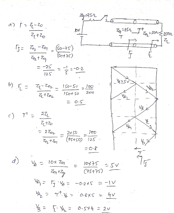

Zg=752 Moo L V E 26=752 I 2 =50ngisor CO? = -20 Ztro Ij = Toz-201, 60-75) : 22 (0+75). = 3:02 b) = quzon - so to you Zt7oz c) pt = 22 Etzo = 2202 – 2x50 2.100 .. z +20 (75+50) 125 =0.8 d) Ug = 10x 20) = 10x75 = 5v Zentley VA, TJ VAD -0.245 =-11 Van = 97.44 = .0.8*5 = 4V B = TV = 0.544 = 20 (75+75) -
57 Osso) = 402 x = F x W3 =' 0.2(2) = 0.41 TX V = 0.52014. = 0.21
Know the answer?
Add Answer to:
HYUNLP 6. In the lossless transmission line system shown, the switch S is closed at t...
Not the answer you're looking for?
Ask your own homework help question.
Our experts will answer your question WITHIN MINUTES for Free.
Similar Homework Help Questions
3. A system of two transmission lines connected in series are driven by a voltage source fi(t) Vo...
 3. A system of two transmission lines connected in series are driven by a voltage source fi(t) Vou(t) and terminated by a resistive load of 60S2 as shown in the figure below. A switch is closed at t 0 and the positive voltages are measured for 5 μs giving the bounce diagram shown in the figure-the voltage values indicated in the diagram correspond to delta function weights times the source voltage products such as VOTg, VOTg(1 +「2), etc. 400 m...
 3. A system of two transmission lines connected in series are driven by a voltage source fi(t) Vou(t) and terminated by a resistive load of 60S2 as shown in the figure below. A switch is closed at t 0 and the positive voltages are measured for 5 μs giving the bounce diagram shown in the figure-the voltage values indicated in the diagram correspond to delta function weights times the source voltage products such as VOTg, VOTg(1 +「2), etc. 400 m...
ADVERTISEMENT
Need Online Homework Help?
Ask
a QuestionGet Answers For Free
Most questions answered within 3 hours.
Most questions answered within 3 hours.
ADVERTISEMENT
ADVERTISEMENT
Active Questions
-
Phosphorous + bromine = phosphorous tribromide. If 35.0 g of
bromine are reacted and 27.9 grams...
asked 1 hour ago -
Derive the long wavelength limit of the Planck energy density
distribution
asked 1 hour ago -
Calculate the pH of each of the following solutions.
0.50 M HBr
3.1×10⁻⁴ M KOH
4.2×10⁻⁵...
asked 4 hours ago -
For the year ended December 31, Depot Max’s cost of merchandise
sold was $85,600. Inventory at the...
asked 4 hours ago -
Week 10 - Professional Memo Assignment
Professional Memo Assignment
Your mission for this week, should you...
asked 4 hours ago -
Write a Python program that stores the data for each
player on the team, and it...
asked 5 hours ago -
In
the last 3 months, mike never knows when he is going to get his
allowance...
asked 5 hours ago -
Is Ca(OH)2 a Bronsted base, Lewis base, or both? Why?
asked 5 hours ago -
1A- Why don’t voters complain about U.S. tariffs on imported
sugar?
Because sugar is only a...
asked 5 hours ago -
Cash Payback Period
Primera Banco is evaluating two capital investment proposals for
a drive-up ATM kiosk,...
asked 5 hours ago -
Create a button in Swift (Xcode) that will create a charge,
create a charge using Stripe's...
asked 5 hours ago -
The reaction rate of CO and NO2 in the reaction
CO(g) + NO2(g) → CO2(g) +...
asked 5 hours ago
ADVERTISEMENT