
Homework Answers

Add Answer to:
Consider the circuit shown in Fig. 1 with Vs=10V. Assume there is no initial energy stored...
just do question 26 and 30 and show all your work (a) Select R so that 26. For the cincuit of Fig. 943,.40 30u-) m v...
 just do question 26 and 30 and show all your work
(a) Select R so that 26. For the cincuit of Fig. 943,.40 30u-) m v(0+) 6 V. (b) Compute (2 ms). (c) Determine the settling time of the capacitor voltage. (d) Is the inductor current settling time the same as your answer to part (c)? 27. The current source in Fig. 9.43 is id) = 101(1-1) μ A. (a) Select Ri such that iLO")-2 μΑ. Compute L at t-500...
just do question 26 and 30 and show all your work
(a) Select R so that 26. For the cincuit of Fig. 943,.40 30u-) m v(0+) 6 V. (b) Compute (2 ms). (c) Determine the settling time of the capacitor voltage. (d) Is the inductor current settling time the same as your answer to part (c)? 27. The current source in Fig. 9.43 is id) = 101(1-1) μ A. (a) Select Ri such that iLO")-2 μΑ. Compute L at t-500...
Problem 5: Consider the circuit shown in the figure below in which the initial inductor current...
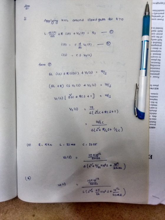
 Problem 5: Consider the circuit shown in the figure below in which the initial inductor current and capacitor voltage are both zero. (a) Write the differential equation for vc(t). (b) Find the particular solution. (c) Is this circuit overdamped, critically damped, or underdamped? 4 0 i(t) vc()
Determine if overdamped,underdamped, or critically damped For the circuit shown below, Vs-200V, R-30, R.-50. C -0.125pF...
 Determine if overdamped,underdamped, or critically damped
For the circuit shown below, Vs-200V, R-30, R.-50. C -0.125pF and L-SmH. Find (a) the initial voltage across the capacitor 20. (b) the initial current through the inductor, lu(0). (e) the damping coefficient and resonant frequency . (d) the initial condition dvede , (e) the voltage across the capacitor (t) for the initial condition diu/dt , and the current through the inductor lu(t) for p R2 Voc
Determine if overdamped,underdamped, or critically damped
For the circuit shown below, Vs-200V, R-30, R.-50. C -0.125pF and L-SmH. Find (a) the initial voltage across the capacitor 20. (b) the initial current through the inductor, lu(0). (e) the damping coefficient and resonant frequency . (d) the initial condition dvede , (e) the voltage across the capacitor (t) for the initial condition diu/dt , and the current through the inductor lu(t) for p R2 Voc
Function Generatr Inductor Model Ra R, Figure 1 Series RLC Circuit Preliminary This laboratory wi...
 Function Generatr Inductor Model Ra R, Figure 1 Series RLC Circuit Preliminary This laboratory will demonstrate how varying resistance changes the natural response of a series RLC circuit (Fig. 1). The function generator is modeled as an ideal voltage source v(t) 5 u() V in series with source resistance Rs-50Q. After measurements using an LCR meter, the inductor is modeled as an ideal L 90 mH inductor in series with resistance RL-20Q. The capacitance is C-0.22 μF. 1) Calculate the...
You are given the circuit shown below. The switch has been at the position shown for...
 You are given the circuit shown below. The switch has been at the position shown for a long time before being moved at t = 0. You are told that C = 0.25F, L = 2H, R1 = 100. LR + VL -+ VR. =O Use the same sort of methodical approach as before: a) Determine i, (0+), vc(0+) and ic(0+) b) Determine di 2007 and doc0* c) Determine the steady-state value for the voltage Vc.final d) Use circuit analysis...
For the following resonant series circuit shown in fig. 1, find : - Quality factor, Q....
 For the following resonant series circuit shown in fig. 1, find : - Quality factor, Q. - Bandwidth, B. - The voltage across the capacitor. - The voltage across the inductor. - The voltage across the resistor. L = 4.7 mH C = 0.001uF S R = 470 VIN-1 V Fig. 1 Resonant series circuit
x=1435 1) In the circuit you have a 250 mH inductor, a X 2 resistor and a 10 nF capacitor. Please find: a. Calculate roots of characteristic equation of the voltage response b. Is it over, under,...
 x=1435
1) In the circuit you have a 250 mH inductor, a X 2 resistor and a 10 nF capacitor. Please find: a. Calculate roots of characteristic equation of the voltage response b. Is it over, under, or critically damped? c. What value of R would you add in series with X to yield a damped frequency of 12 krad/sec? d. What value of R would you add in series with X to yield a critically damped response?
1) In...
x=1435
1) In the circuit you have a 250 mH inductor, a X 2 resistor and a 10 nF capacitor. Please find: a. Calculate roots of characteristic equation of the voltage response b. Is it over, under, or critically damped? c. What value of R would you add in series with X to yield a damped frequency of 12 krad/sec? d. What value of R would you add in series with X to yield a critically damped response?
1) In...
9. For the given circuit, if the initial voltage across the capacitor is vc(0*) = 0,...
 9. For the given circuit, if the initial voltage across the capacitor is vc(0*) = 0, find an expression for the voltrage across the capacitor as a function of time and graph voltage versus time. R= 100 k2 w v=100 V uc) C = 0.01 uF 10. If a 100-F capacitance is initially charged to 1000V and at t=0, it is connected to a 1-ka resistance, at what time has 50 percent of the initial energy stored in the capacitance...
For the circuit in Fig. 1: 3.2 kQ 2 kQ w ww 18 kQ 0.8 pF...
 For the circuit in Fig. 1: 3.2 kQ 2 kQ w ww 18 kQ 0.8 pF 40 V Fig. 1 1. Determine the expression for the voltage across the capacitor, v), for t20 by any method. Show the complete derivation of the solution and a graph of ve(t)
The switch in the circuit shown in Fig. Shown has been in position a for a...
 The switch in the circuit shown in Fig. Shown has been in position a for a long time. At t-o the switch is moved to position b. a) What is the initial value of vc? b) What is the final value of vc? c) What is the time constant of the circuit when the switch is in position a? d) What is the expression for vc(t) when t > 0? 80 V 315 kn 100 V 2F What is the...
 just do question 26 and 30 and show all your work
(a) Select R so that 26. For the cincuit of Fig. 943,.40 30u-) m v(0+) 6 V. (b) Compute (2 ms). (c) Determine the settling time of the capacitor voltage. (d) Is the inductor current settling time the same as your answer to part (c)? 27. The current source in Fig. 9.43 is id) = 101(1-1) μ A. (a) Select Ri such that iLO")-2 μΑ. Compute L at t-500...
just do question 26 and 30 and show all your work
(a) Select R so that 26. For the cincuit of Fig. 943,.40 30u-) m v(0+) 6 V. (b) Compute (2 ms). (c) Determine the settling time of the capacitor voltage. (d) Is the inductor current settling time the same as your answer to part (c)? 27. The current source in Fig. 9.43 is id) = 101(1-1) μ A. (a) Select Ri such that iLO")-2 μΑ. Compute L at t-500...
 Problem 5: Consider the circuit shown in the figure below in which the initial inductor current and capacitor voltage are both zero. (a) Write the differential equation for vc(t). (b) Find the particular solution. (c) Is this circuit overdamped, critically damped, or underdamped? 4 0 i(t) vc()
 Determine if overdamped,underdamped, or critically damped
For the circuit shown below, Vs-200V, R-30, R.-50. C -0.125pF and L-SmH. Find (a) the initial voltage across the capacitor 20. (b) the initial current through the inductor, lu(0). (e) the damping coefficient and resonant frequency . (d) the initial condition dvede , (e) the voltage across the capacitor (t) for the initial condition diu/dt , and the current through the inductor lu(t) for p R2 Voc
Determine if overdamped,underdamped, or critically damped
For the circuit shown below, Vs-200V, R-30, R.-50. C -0.125pF and L-SmH. Find (a) the initial voltage across the capacitor 20. (b) the initial current through the inductor, lu(0). (e) the damping coefficient and resonant frequency . (d) the initial condition dvede , (e) the voltage across the capacitor (t) for the initial condition diu/dt , and the current through the inductor lu(t) for p R2 Voc
 Function Generatr Inductor Model Ra R, Figure 1 Series RLC Circuit Preliminary This laboratory will demonstrate how varying resistance changes the natural response of a series RLC circuit (Fig. 1). The function generator is modeled as an ideal voltage source v(t) 5 u() V in series with source resistance Rs-50Q. After measurements using an LCR meter, the inductor is modeled as an ideal L 90 mH inductor in series with resistance RL-20Q. The capacitance is C-0.22 μF. 1) Calculate the...
 You are given the circuit shown below. The switch has been at the position shown for a long time before being moved at t = 0. You are told that C = 0.25F, L = 2H, R1 = 100. LR + VL -+ VR. =O Use the same sort of methodical approach as before: a) Determine i, (0+), vc(0+) and ic(0+) b) Determine di 2007 and doc0* c) Determine the steady-state value for the voltage Vc.final d) Use circuit analysis...
 For the following resonant series circuit shown in fig. 1, find : - Quality factor, Q. - Bandwidth, B. - The voltage across the capacitor. - The voltage across the inductor. - The voltage across the resistor. L = 4.7 mH C = 0.001uF S R = 470 VIN-1 V Fig. 1 Resonant series circuit
 x=1435
1) In the circuit you have a 250 mH inductor, a X 2 resistor and a 10 nF capacitor. Please find: a. Calculate roots of characteristic equation of the voltage response b. Is it over, under, or critically damped? c. What value of R would you add in series with X to yield a damped frequency of 12 krad/sec? d. What value of R would you add in series with X to yield a critically damped response?
1) In...
x=1435
1) In the circuit you have a 250 mH inductor, a X 2 resistor and a 10 nF capacitor. Please find: a. Calculate roots of characteristic equation of the voltage response b. Is it over, under, or critically damped? c. What value of R would you add in series with X to yield a damped frequency of 12 krad/sec? d. What value of R would you add in series with X to yield a critically damped response?
1) In...
 9. For the given circuit, if the initial voltage across the capacitor is vc(0*) = 0, find an expression for the voltrage across the capacitor as a function of time and graph voltage versus time. R= 100 k2 w v=100 V uc) C = 0.01 uF 10. If a 100-F capacitance is initially charged to 1000V and at t=0, it is connected to a 1-ka resistance, at what time has 50 percent of the initial energy stored in the capacitance...
 For the circuit in Fig. 1: 3.2 kQ 2 kQ w ww 18 kQ 0.8 pF 40 V Fig. 1 1. Determine the expression for the voltage across the capacitor, v), for t20 by any method. Show the complete derivation of the solution and a graph of ve(t)
 The switch in the circuit shown in Fig. Shown has been in position a for a long time. At t-o the switch is moved to position b. a) What is the initial value of vc? b) What is the final value of vc? c) What is the time constant of the circuit when the switch is in position a? d) What is the expression for vc(t) when t > 0? 80 V 315 kn 100 V 2F What is the...
Most questions answered within 3 hours.
-
The mean waiting time at the drive-through of a fast-food
restaurant from the time an order...
asked 10 minutes ago -
The pitch (p) of a helix is defined as p = dn, in which n is...
asked 12 minutes ago -
Do you agree that the declining stock of social capital is the
blame for the failure...
asked 15 minutes ago -
A researcher is interested in whether coffee consumption helps
with performance on reading comprehension tasks. The...
asked 25 minutes ago -
it has been estimated since the beginning of the human race that
about 133 metric ton...
asked 31 minutes ago -
Where must Medicare prescription drug plans allow for
participants to fill their prescriptions?
asked 34 minutes ago -
Five moles of monatomic ideal gas have initial pressure 2.50 ×
103 Pa and initial volume...
asked 49 minutes ago -
A resistor and the capacitor are used to control the timing in
the RC circuit of...
asked 48 minutes ago -
Living in a group could bring several disadvantages to an
individual. What are some of the...
asked 1 hour ago -
Complete and balance the following reactions. In case of no
reaction occurring write NR.
Mix #1:...
asked 1 hour ago -
If an economy consumes 75% of any increase in income, then an
increase in autonomous investment...
asked 1 hour ago -
A shotputter throws the shot with an initial speed of 15.8 m/s
at a 38.0 ∘...
asked 1 hour ago