Question
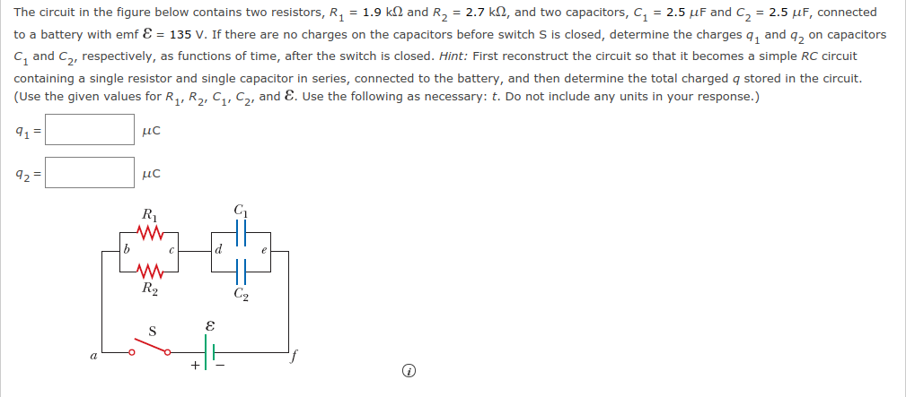
The circuit in the figure below contains two resistors, R1 = 1.9 kΩ and R2 = 2.7 kΩ, and two capacitors, C1 = 2.5 ?F and C2 = 2.5 ?F, connected to a battery with emf e m f = 135 V. If there are no charges on the capacitors before switch S is closed, deter
Homework Answers

Know the answer?
Add Answer to:
The circuit in the figure below contains two resistors, R1 = 1.9 kΩ and R2 = 2.7 kΩ, and two capacitors, C1 = 2.5 ?F and C2 = 2.5 ?F, connected to a battery with emf e m f = 135 V. If there are no charges on the capacitors before switch S is closed, deter
Not the answer you're looking for?
Ask your own homework help question.
Our experts will answer your question WITHIN MINUTES for Free.

ADVERTISEMENT
Need Online Homework Help?
Ask
a QuestionGet Answers For Free
Most questions answered within 3 hours.
Most questions answered within 3 hours.
ADVERTISEMENT
ADVERTISEMENT
Active Questions
-
Calculate the approximate number of residues of Rubisco, which
is involved in carbon fixation in plants,...
asked 1 minute from now -
Other decisions about scientific claims can have a much broader
impact.ENERGYarrow-10x10.png, environment, health, security - all...
asked 53 minutes ago -
I need to write a research paper and work cited about this
topic: The United States...
asked 1 hour ago -
Hello! I was wondering if I could have some help?
If the vapor pressure of carvone...
asked 1 hour ago -
An economist wants to estimate the mean per capita income (in
thousands of dollars) for a...
asked 1 hour ago -
What would be the input/output characteristic of a circuit
obtained by putting two of your 2's-complementers...
asked 1 hour ago -
In Drosophila, the transition from the syncytial blastoderm
stage to the cellular blastoderm stage is a...
asked 2 hours ago -
Project management question:
Name 3 different types of resources (hint: humans are one
type)
asked 2 hours ago -
Consider the following reaction: C 2H 2( g) + 2H 2( g) C 2H 6(
g)...
asked 2 hours ago -
Consider a 1.0 L buffer containing 0.092 mol L-1 HCOOH and 0.100
mol L-1 HCOO-. What...
asked 2 hours ago -
Koch Realty has owned a vacant land with a FMV of
$775,000 and an adjusted basis...
asked 2 hours ago -
It is estimated 29% of all adults in United States invest in
stocks and that 85%...
asked 2 hours ago
ADVERTISEMENT