
Homework Answers

Add Answer to:
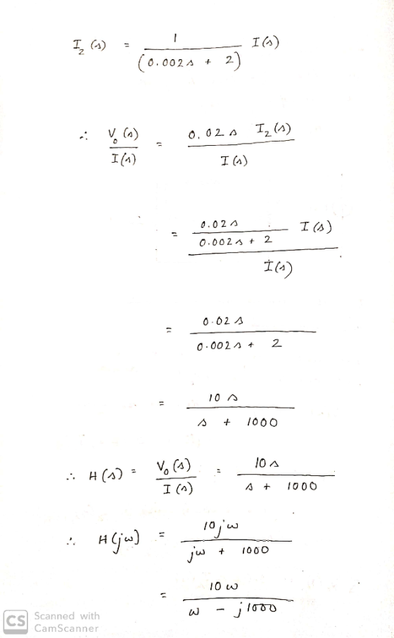
Given the circuit in Figure 5 and 1(t) = Icos(ωt) A, find the transfer function H(ω)...
5. Given the circuit in Figure 5 and i(t) = I cos(@t) A, find the transfer...
 5. Given the circuit in Figure 5 and i(t) = I cos(@t) A, find the transfer function H(w) = V/I 10 22 WW + i(t) 10 22 vo(t) 20 mH Figure 5
Find the transfer function Vo(s)/V(s) for the circuit shown in the figure. 1. IH OO00 H...
 Find the transfer function Vo(s)/V(s) for the circuit shown in the figure. 1. IH OO00 H w 0000 TH IF IF
For the circuit shown in Figure 1, determine (a) The transfer function H(s) Vo(s)/V(s) 1 (b)....
 For the circuit shown in Figure 1, determine (a) The transfer function H(s) Vo(s)/V(s) 1 (b). The impulse response h(t) given that R,-5Q, R2-2Q, L,-1 mH, and L2 = 2 mH Ri L R2 Figure 1.
Use the node-voltage method to find the steady-state expression for vo(t) in the circuit in (Figure...
 Use the node-voltage method to find the steady-state expression
for vo(t) in the circuit in (Figure 1) if
vg1= 10 sin(400t+143.13∘)V,
vg2= 18.03cos(400t+33.69∘)V.
Write the steady-state expression for vo(t) as vo=Vocos(ωt+ϕ),
where −180∘<ϕ≤180∘.
Find the numerical value of Vo.
Find the numerical value of ϕ.
Find the numerical value of ω.
50 mH 1500
Use the node-voltage method to find the steady-state expression
for vo(t) in the circuit in (Figure 1) if
vg1= 10 sin(400t+143.13∘)V,
vg2= 18.03cos(400t+33.69∘)V.
Write the steady-state expression for vo(t) as vo=Vocos(ωt+ϕ),
where −180∘<ϕ≤180∘.
Find the numerical value of Vo.
Find the numerical value of ϕ.
Find the numerical value of ω.
50 mH 1500
Question 1 For the circuit shown in figure 1; i. Find the transfer impedance function, H(s)...
 Question 1 For the circuit shown in figure 1; i. Find the transfer impedance function, H(s) = Vds(s) Find the poles and zeros for this transfer function and plot them on the s - Find the magnitude of the transfer function in decibels. [10] s-plane [8] ii [3] 2H 20 20 2 H Figure Question 2 The hybrid parameters (h-parameters) for the two -port network circuit in figure 2 are; 5 h=2 0.05 Find the equivalent impedance parameters (z-parameters) Find...
3. Given the circuit in Figure 3, find v(t) for all t>0. t=0 v(t) 4 A...
 3. Given the circuit in Figure 3, find v(t) for all t>0. t=0 v(t) 4 A 20 22 60 Ω 0000 15 H 1/30 F HL
Q1. For the filter circuit shown below, (5 marks) Vo(s) a) Find the transfer function, G(s)...
 Q1. For the filter circuit shown below, (5 marks) Vo(s) a) Find the transfer function, G(s) and the type of the filter. (4 marks) Vi(s)' b) Find the initial and final values of vo(t) if vi(t) = 2u(t). (1 marks) 10 k12 w 6 тн 0000 v;(1) 5 k92 2 mF
2. For the circuit shown in Figure 2: (a) (5 points) Calculate the transfer function H(s)-Volo)/V(o)....
 2. For the circuit shown in Figure 2: (a) (5 points) Calculate the transfer function H(s)-Volo)/V(o). (b) (5 points) Find vo(t) due to a unit step input using the residue method. (e) (5 points) Find vo(t) due to a unit ramp input using the residue method. (d) (10 points) If v(t) 5/5 cos(2t-33.43499) V, find the steady-state expression for volt). R2 R1 2Ω 2Ω L 2H Volt) С 0.5F
please write clearly b.) Find the transfer function, Vo(s)/V(s), for the circuit in the figure below....
 please write clearly
b.) Find the transfer function, Vo(s)/V(s), for the circuit in the figure below. 10000 0000 (8)
please write clearly
b.) Find the transfer function, Vo(s)/V(s), for the circuit in the figure below. 10000 0000 (8)
1. Find the numerical expression for the transfer function from Vi(t) to V.(t), for each circuit ...
 1. Find the numerical expression for the transfer function from Vi(t) to V.(t), for each circuit below, and sketch the magnitude and phase of the transfer function, as functions of w. For these plots, show the w axis on a log 10 scale, and show the amplitude of the transfer function on a decibel scale. 0.1uF V(t) 0.1 uF 250mH V(t) 250mH 2k2 V(t) 10k2 0.25μF Vo(t)
1. Find the numerical expression for the transfer function from Vi(t) to V.(t),...
1. Find the numerical expression for the transfer function from Vi(t) to V.(t), for each circuit below, and sketch the magnitude and phase of the transfer function, as functions of w. For these plots, show the w axis on a log 10 scale, and show the amplitude of the transfer function on a decibel scale. 0.1uF V(t) 0.1 uF 250mH V(t) 250mH 2k2 V(t) 10k2 0.25μF Vo(t)
1. Find the numerical expression for the transfer function from Vi(t) to V.(t),...
 5. Given the circuit in Figure 5 and i(t) = I cos(@t) A, find the transfer function H(w) = V/I 10 22 WW + i(t) 10 22 vo(t) 20 mH Figure 5
 Find the transfer function Vo(s)/V(s) for the circuit shown in the figure. 1. IH OO00 H w 0000 TH IF IF
 For the circuit shown in Figure 1, determine (a) The transfer function H(s) Vo(s)/V(s) 1 (b). The impulse response h(t) given that R,-5Q, R2-2Q, L,-1 mH, and L2 = 2 mH Ri L R2 Figure 1.
 Use the node-voltage method to find the steady-state expression
for vo(t) in the circuit in (Figure 1) if
vg1= 10 sin(400t+143.13∘)V,
vg2= 18.03cos(400t+33.69∘)V.
Write the steady-state expression for vo(t) as vo=Vocos(ωt+ϕ),
where −180∘<ϕ≤180∘.
Find the numerical value of Vo.
Find the numerical value of ϕ.
Find the numerical value of ω.
50 mH 1500
Use the node-voltage method to find the steady-state expression
for vo(t) in the circuit in (Figure 1) if
vg1= 10 sin(400t+143.13∘)V,
vg2= 18.03cos(400t+33.69∘)V.
Write the steady-state expression for vo(t) as vo=Vocos(ωt+ϕ),
where −180∘<ϕ≤180∘.
Find the numerical value of Vo.
Find the numerical value of ϕ.
Find the numerical value of ω.
50 mH 1500
 Question 1 For the circuit shown in figure 1; i. Find the transfer impedance function, H(s) = Vds(s) Find the poles and zeros for this transfer function and plot them on the s - Find the magnitude of the transfer function in decibels. [10] s-plane [8] ii [3] 2H 20 20 2 H Figure Question 2 The hybrid parameters (h-parameters) for the two -port network circuit in figure 2 are; 5 h=2 0.05 Find the equivalent impedance parameters (z-parameters) Find...
 3. Given the circuit in Figure 3, find v(t) for all t>0. t=0 v(t) 4 A 20 22 60 Ω 0000 15 H 1/30 F HL
 Q1. For the filter circuit shown below, (5 marks) Vo(s) a) Find the transfer function, G(s) and the type of the filter. (4 marks) Vi(s)' b) Find the initial and final values of vo(t) if vi(t) = 2u(t). (1 marks) 10 k12 w 6 тн 0000 v;(1) 5 k92 2 mF
 2. For the circuit shown in Figure 2: (a) (5 points) Calculate the transfer function H(s)-Volo)/V(o). (b) (5 points) Find vo(t) due to a unit step input using the residue method. (e) (5 points) Find vo(t) due to a unit ramp input using the residue method. (d) (10 points) If v(t) 5/5 cos(2t-33.43499) V, find the steady-state expression for volt). R2 R1 2Ω 2Ω L 2H Volt) С 0.5F
 please write clearly
b.) Find the transfer function, Vo(s)/V(s), for the circuit in the figure below. 10000 0000 (8)
please write clearly
b.) Find the transfer function, Vo(s)/V(s), for the circuit in the figure below. 10000 0000 (8)
 1. Find the numerical expression for the transfer function from Vi(t) to V.(t), for each circuit below, and sketch the magnitude and phase of the transfer function, as functions of w. For these plots, show the w axis on a log 10 scale, and show the amplitude of the transfer function on a decibel scale. 0.1uF V(t) 0.1 uF 250mH V(t) 250mH 2k2 V(t) 10k2 0.25μF Vo(t)
1. Find the numerical expression for the transfer function from Vi(t) to V.(t),...
1. Find the numerical expression for the transfer function from Vi(t) to V.(t), for each circuit below, and sketch the magnitude and phase of the transfer function, as functions of w. For these plots, show the w axis on a log 10 scale, and show the amplitude of the transfer function on a decibel scale. 0.1uF V(t) 0.1 uF 250mH V(t) 250mH 2k2 V(t) 10k2 0.25μF Vo(t)
1. Find the numerical expression for the transfer function from Vi(t) to V.(t),...
Most questions answered within 3 hours.
-
Please help me with FLOWCHART and UML diagram for class,
thank you!
#include <iostream>
#include <fstream>...
asked 16 minutes ago -
3. Describe the “logic circuit” of the Lac operon. Which
proteins are bound or not to...
asked 17 minutes ago -
Ayesha’s adjusted gross income is $60,000 in 2019. She donated a
piece of artwork with a...
asked 23 minutes ago -
For Dijkstra’s shortest path algorithm:
a. Give the Big-O time for Dijkstra’s shortest path algorithm
and...
asked 36 minutes ago -
Phosphorus violates the 'octet rule' in biological molecules,
forming more covalent bonds than expected based on...
asked 39 minutes ago -
A 1.3 eV electron has a 10-4 probability of tunneling
through a 2.4 eV potential barrier....
asked 57 minutes ago -
What is the one ingredient that is common to being successful
with all stakeholders?
profit
trust...
asked 56 minutes ago -
Write an assembly language 32 bit program that reads in lines of
text by a .txt...
asked 59 minutes ago -
what is the density ( in g/L) of hydrogen gas at 29 degrees C and a...
asked 1 hour ago -
5-6. You are considering three investment alternatives for some
spare cash: Old Reliable Corporation stock (A1),...
asked 59 minutes ago -
Problem 16-02
Receivables Investment
Medwig Corporation has a DSO of 45 days. The company averages
$7,250...
asked 1 hour ago -
Mr. Brown hired Lowe's Maintenance Services Limited to repair
and paint the exterior wall of his...
asked 1 hour ago